The OPC UA connector enables the MetaDefender Optical Diode (hereinafter Optical Diode) to retrieve OPC UA data from a customer-owned OPC UA server in the BLUE zone, transfer the data across the Optical Diode, and replicate the data to customer-owned clients in the RED zone. The OPC UA Connector resides on the Optical Diode BLUE and RED nodes.
On Optical Diode BLUE, the OPC UA Connector acts as a client. It extracts data from a customer-owned OPC UA server in the BLUE zone and transfers that information to the Optical Diode RED. On Optical Diode RED, the OPC UA Connector acts as a server. It receives information from the Optical Diode BLUE and makes the information available to customer-owned OPC UA clients in the RED zone. The OPC UA connector supports connecting to up to 5 OPC UA servers (3 on Din Rail form factors) simultaneously, in a 1:1 relationship.
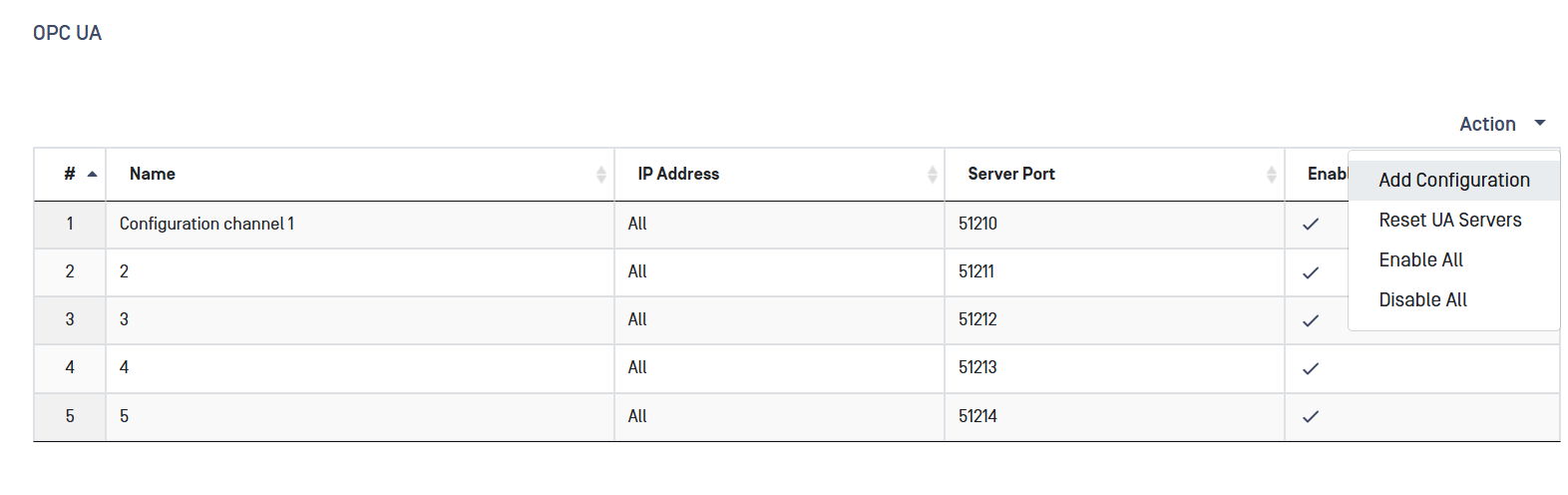
To configure the Optical Diode OPC UA connector click on OPC UA section in the menu. This procedure is performed on both BLUE and RED sides.
Optical Diode BLUE
A security dongle must be inserted in the BLUE side to change configuration.
This section describes configuration of the Optical Diode BLUE OPC UA client to communicate with the customer-owned OPC UA server in the BLUE zone.
Initial Configuration
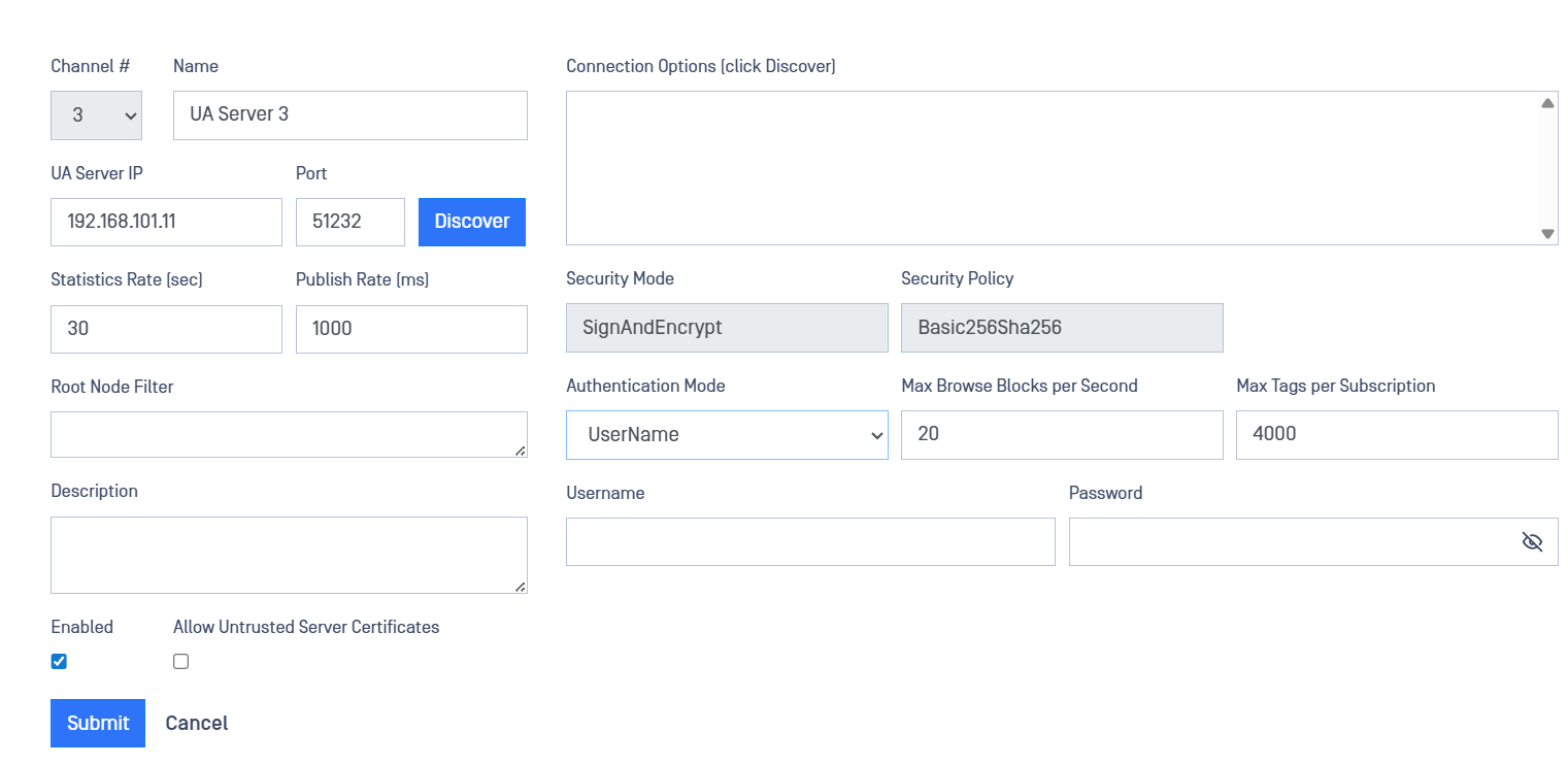
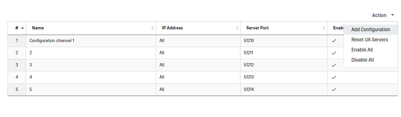
Navigate to the OPC UA menu item under the Connectors menu, In the Action menu, select Add Configuration. Fill in the following fields:
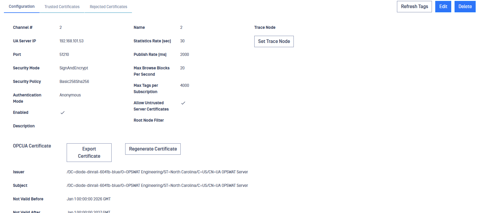
- Channel #: Assign a channel number for the configured data flow. Note that the OPC UA channel number must be the same on BLUE and RED.
- Name: Assign a "Friendly Name" for the OPC UA configuration (not mandatory).
- UA Server IP: Type the IP address of the customer’s OPC UA server in the UA Server IP box.
- Port: Type the port number of the customer’s OPC UA server in the Port Number box.
- Click on the Discover button. Optical Diode BLUE connects to the OPC UA server. Available connections will appear in the Connection Options box. Select the connection to be configured and the security mode and policy supported by that server will appear in the boxes below.
- Security mode. The Security Mode and (if applicable), the Security Policy will be auto populated based on the Connection selected.
- Statistics Rate: Type a value in the Statistics Rate box to generate OPC UA statistics. This value determines how often statistics are output to the Events log. If you type 0, statistics will not be generated.
- Publish Rate: Type a value in the Publish Rate box to determine the rate (in milliseconds) that the OPC UA client on Optical Diode BLUE can receive data from the customer-owned OPC UA server in the BLUE zone. Default value is 1000.
- Authentication Mode: Select Anonymous to allow all users. Select Username to allow a specific user. If you select Username, the Username and Password fields enable. Type the username and associated password you want to allow.
- Root Node Filter: To replicate data from only certain nodes on the OPC UA server in the BLUE zone, type one or more node names in the Root Node Filter box. Data will be retrieved from each typed node, and all of their child nodes, for replication to the RED zone. If the box is left blank (default), OPC UA data is retrieved from all nodes on the server.
- Description: Key in a detailed description of the configuration (not mandatory).
- Max Browse Blocks per Second: Type the rate at which the OPC UA schema is sent from Blue To Red. Recommended value is 15 blocks per second. If stack overflow syslog messages start appearing on either Red or Blue, reduce the block count to 10 blocks per second.
- Max Tags per Subscription: Max Tags involves the capability of the individual OPC UA Server that we are connecting to from BLUE. OPC UA Servers have a limit on the number of tags per subscription, as well as the number of subscriptions. The default value is 4000. If syslog reports an error of max subscriptions reached, increase the Max Tags to 6000 and try again. If syslog reports an error of subscription too large, reduce the Max Tags value.
- All filter values are case-insensitive.
- You can type multiple node names in the Root Node Filter box.
- You can type only one node name in the Trace Node box. This field is not mandatory.
- Separate multiple node names with a semi-colon.
- Changing filter information restarts Optical Diode BLUE. This process takes about one minute.
If a tag on the OPC UA server changes 10 times/second (100 ms), and the Publish Rate is 1000 ms, the client receives one value/second. If the Publish Rate is 50 ms, the client receives 20 values/second. Since the tag only changes 10 times/second, the client receives 10 values/second.
Click the Submit button to save the changes. After you click Submit, if all connections are correct, the boxes in the OPC UA Status area should populate after about one minute and the certificate will be available to download.
Install Trusted Certificate
Trusted certificates must be installed on the OPC UA client on Optical Diode BLUE and the Optical Diode OPC UA server on RED. Refer to Pages 27 and 28 of the OPC Unified Architecture document, authored by the OPC Foundation, for information on management and transfer of certificate information between the OPC UA server and OPC UA client.
- Once an OPC UA configuration is successfully Submitted, Optical Diode BLUE will generate a trusted certificate.
- Click the Export button to save a copy of the certificate to your desktop. This certificate will be used later for configuring Optical Diode RED.
- Install the certificate on the customer-owned OPC UA server.
A Trusted Certificate must be provided for each configured Channel.
Click the Enable checkbox Allow Untrusted Server Certificates to allow untrusted certificates on the OPC UA server. The default is disabled.
Configure Multiple OPC UA Servers BLUE
On BLUE, navigate to the OPC UA menu item under the Connectors menu, Select Add Configuration from the Action menu.
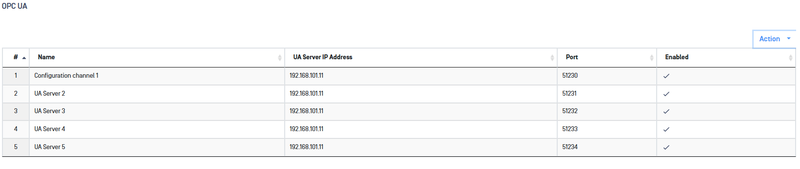
Repeat the steps outlined in the Initial BLUE Configuration section above to add additional OPC UA servers.
Refresh Tags
When names of the tags are changed on the BLUE side customer-owned OPC UA server, the tags need to be refreshed so that the OPC UA BLUE client can collect data for the changed tags. Click on the Refresh Tags button to clear the cache allowing the correct transfer of tag information.
Optical Diode RED
A security dongle must be inserted in the RED side to change configuration.
This section describes configuration of the Optical Diode OPC UA RED server to transfer OPC UA data to the customer-owned OPC UA client(s) in the RED zone.
Initial Configuration
Navigate to the OPC UA section under the Connectors menu. On the right hand side "Action" menu select "Add Configuration".
Fill in the following fields:
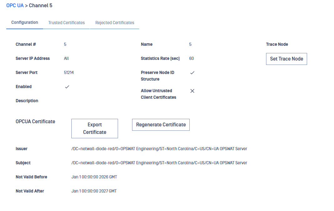
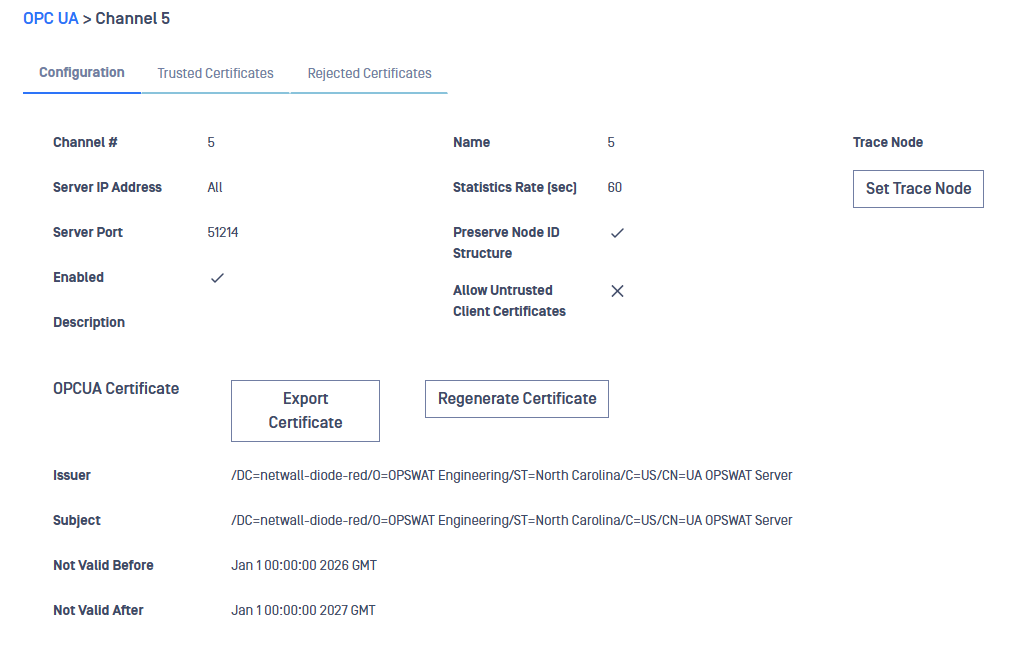
- Channel Number: Assign a Channel Number for the configured data flow. Note that the OPC UA channel number must be the same on BLUE and RED.
- Name: Assign a friendly name (not mandatory)
- IP Address: IP Address dropdown. Lets a user choose which IP address the OPC-UA server will listen on RED side. Or ANY to allow connections on any interface/IP.
- Server Port: Type the Optical Diode RED port number in the Port box. The customer-owned OPC UA clients will connect to this node.
- Statistics Rate: Type a value in the Statistics Rate box if you want to generate OPC UA statistics. If you type 0, statistics will not be generated.
- Trace Node: if you want to trace data generated from an individual node, type the name of a node on the OPC UA server in the BLUE zone in the Trace Node box. This field is not mandatory and can be empty.
- Preserve Node ID Structure: Click the Preserve Node ID Structure checkbox if you want to preserve the Node ID structure for each tag on the customer-owned OPC UA server in the BLUE zone. If you do not click this checkbox, the OPC UA server on the Optical Diode RED will create its own Node ID references for each tag.
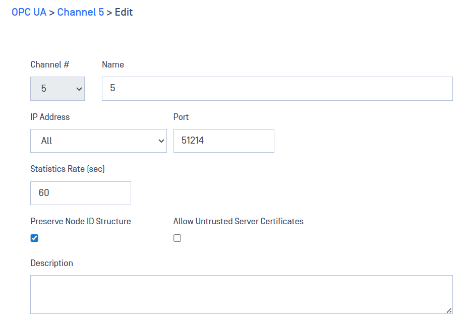
- Click Submit to save the configuration.
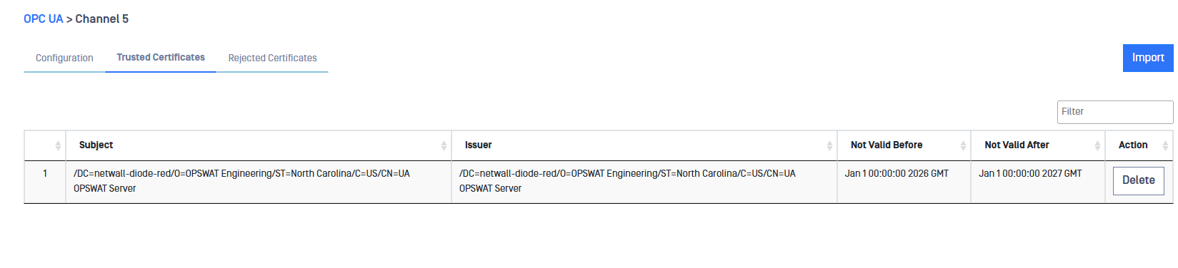
Install Trusted Certificate
A trusted certificate must be installed on the Optical Diode RED OPC UA server.
- Generate a certificate on customer-owned OPC UA client and save it to your desktop.
- Import the certificate from your desktop to the Optical Diode RED OPC UA server by clicking the Import button.
A Trusted Certificate must be assigned to each data Channel Number.
Configure Multiple OPC UA Servers RED
- On Optical Diode RED, navigate to the OPC UA menu item under the Connectors menu.
- Select Add Configuration from the Action menu.
- Repeat the steps outlined in the Initial RED Configuration section above to add additional OPC UA servers.
A maximum of 5 OPC UA servers can be configured on rack mount server form factors and a maximum of 3 OPC UA servers can be configured on Din Rail form factors.