IEC 104 Connector allows you to transfer IEC-104 data unidirectionally across the MetaDefender Optical Diode. The IEC-104 Connector is configured on the Optical Diode BLUE and RED side.
The IEC-104 Connector on the Optical Diode BLUE collects data from customer-owned IEC-104 controlled stations in the BLUE zone and transfers that data to the IEC-104 Connector configured on the Optical Diode RED. Customer-owned IEC-104 controlling stations in the RED zone connect to the IEC-104 Connector to monitor the transferred data.
Please, take into consideration that APDUs with time tag will only be received on the RED side with Cause of Transmission set to Spontaneous.
APDUs that could be affected by this are:
M_SP_NA_1=1, M_SP_TA_1=2, M_DP_NA_1=3, M_DP_TA_1=4, M_ST_NA_1=5, M_ST_TA_1=6, M_BO_NA_1=7, M_BO_TA_1=8, M_ME_NA_1=9, M_ME_TA_1=10, M_ME_NB_1=11, M_ME_TB_1=12, M_ME_NC_1=13, M_ME_TC_1=14, M_IT_NA_1=15, M_IT_TA_1=16, M_EP_TA_1=17, M_EP_TB_1=18, M_EP_TC_1=19, M_PS_NA_1=20, M_ME_ND_1=21, M_SP_TB_1=30, M_DP_TB_1=31, M_ST_TB_1=32, M_BO_TB_1=33,M_ME_TD_1=34, M_ME_TE_1=35, M_ME_TF_1=36, M_IT_TB_1=37, M_EP_TD_1=38, M_EP_TE_1=39, M_EP_TF_1=40, P_ME_NA_1=110, P_ME_NB_1=111, P_ME_NC_1=112.
Optical Diode BLUE
A security dongle must be inserted in the BLUE and RED servers to change configuration.
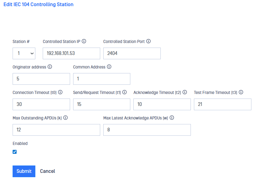
Navigate to the IEC104 menu item under the Connectors menu, In the Action menu, select Add Controlling Station.
Type values in the following boxes:
Station # (Channel): Channel of the IEC-104 stream, this should be the same channel in both BLUE and RED sides.
Controlled Station IP: IP address of the customer-owned IEC 104 Controlled station that the IEC-104 Connector will collect data from.
Controlled Station Port: IEC-104 port of the controlled station on the IEC-104 Connector. Default: 2404.
Originator address: IEC-104 address to identify the originator. Valid values are from 1 to 255.
Common Address: Is the application address of the client (logical station) that must match the address defined in the client configuration. This is defined as the address of the controlling station in the control direction. Valid values are from 1 to 65536.
Connection Timeout (t0): Default value for connection establishment timeout is 30 secs. Valid values are from 1 to 255 secs.
Send/Request Timeout (t1): Default value for sending or testing APDUs is 15 secs. Valid values are from 1 to 255 secs.
Acknowledge Timeout (t2): This is a timeout for acknowledges in case of no data messages and the default value is 10 secs. Valid values are from 1 to 255 secs.
Test Frame Timeout (t3): Timeout for sending test frames in case of a long idle state. Default value is 20 secs and valid values are from 1 to 172801 secs.
Max Outstanding APDUs (k): The IEC-104 client does not send more APDUs if the maximum number of ADPUs have been transmitted and have not been acknowledged. The default value is 12 APDUs.
Max Latest Acknowledge APDUs (w): This setting works in conjunction with t2 to limit how often the IEC-104 client acknowledges APDUs. Increasing this setting can reduce bandwidth required for acknowledging. Default value is 8 APDUs.
Click the Submit button to save the changes.
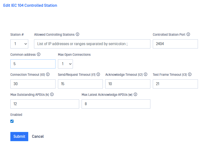
Optical Diode RED
A security dongle must be inserted in the BLUE and RED servers to change configuration.
Navigate to the IEC104 menu item under the Connectors menu, In the Action menu, select Add Controlled Station.
Type values in the following boxes:
Station # (Channel): Channel of the IEC-04 stream, this should be the same channel in both sides, RED and BLUE.
Allowed Controlling Station IP: IP address of the customer-owned IEC-104 Controlling station OPSWAT IEC-104 connector will collect data from. Several controlling stations can be configured.
Controlled Station Port: IEC-104 port on the OPSWAT IEC-104 connector.
Common address: In the RED side originator and common addresses have to share the same value. Valid values are from 1 to 65334.
Max Open Connection: Max. number of controlling stations that can be connected simultaneously.
Connection Timeout (t0): Default value for connection establishment timeout is 30 secs. Valid values are from 1 to 255 secs.
Send/Request Timeout (t1): Default value for sending or testing APDUs is 15 secs. Valid values are from 1 to 255 secs.
Acknowledge Timeout (t2): This is a timeout for acknowledges in case of no data messages and the default value is 10 secs. Valid values are from 1 to 255 secs.
Test Frame Timeout (t3): Timeout for sending test frames in case of a long idle state. Default value is 20 secs and valid values are from 1 to 172801 secs.
Max Outstanding APDUs (k): The IEC 104 client does not send more APDUs if the maximum number of ADPUs have been transmitted and have not been acknowledged. The default value is 12 APDUs.
Max Latest Acknowledge APDUs (w): This setting works in conjunction with t2 to limit how often the IEC 104 client acknowledges APDUs. Increasing this setting can reduce bandwidth required for acknowledging. Default value is 8 APDUs.
Enabled: IEC 104 Connector can be enabled/disabled using this checkbox
Click the Submit button to save the changes.