DNP3 Connector allows you to transfer DNP3 data unilaterally across NetWall. DNP3 Connector is configured on the MetaDefender Optical Diode (hereinafter Optical Diode) BLUE and RED nodes.
The DNP3 Connector on the Optical Diode BLUE collects data from customer-owned DNP3 outstations in the BLUE zone and transfers that data to the DNP3 Connector configured on Optical Diode RED. Th customer-owned DNP3 master in the RED zone connects to the DNP3 Connector to monitor the transferred data.
Please note that the Optical Diode BLUE supports Class 0, 1, 2 and 3 polls, but when transferring to RED all points will be assigned to Class 1. The Diode RED will send unsolicited responses if it is enabled by the Master.
Optical Diode BLUE
A security dongle must be inserted in the BLUE and RED servers to change configuration.
Login into MetaDefender Optical Diode BLUE.
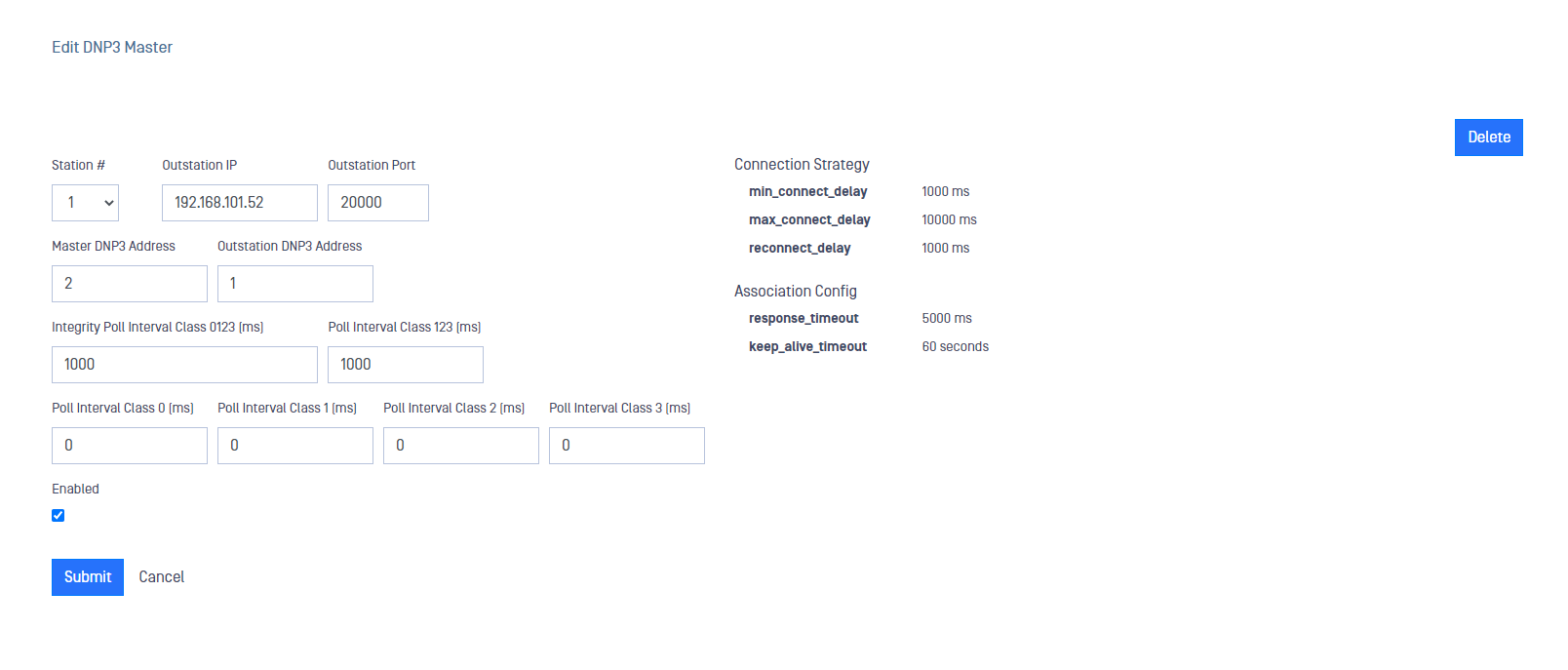
Go to DNP3 menu deploy Action button and select Add Master.
Type values in the following boxes:
Station #: Is similar to the Channel concept in other connectors or streams. Station # needs to be the same in both sides, RED and BLUE.
Outstation IP: IP address of the customer-owned DNP3 Outstation OPSWAT DNP3 connector will collect data from.
Outstation Port: DNP3 port where the customer-owned DNP3 Outstation is configured to listen. Default value is 20000.
Master DNP3 Address: DNP3 address (this is not an IP) to identify the master. Valid values are from 0 to 65519.
Outstation DNP3 Address: Is the DNP3 address (not IP) of the customer-owned DNP3 Outstation that must match the address defined in the client configuration. Valid values are from 1 to 65519. Outstation Address should be different than Master Address.
Integrity Poll Interval Class 0123 [ms]: An integrity Poll will be executed periodically as indicated in this field. An integrity poll requests all event data and the static data of all points assigned to one of the four classes (Classes 0, 1, 2 and 3). A value of 0 ms implies no Poll. If you decide to set up a value different from 0, it needs to be 100ms or bigger.
Poll Interval Class 123 [ms]: Request all event data (corresponding to classes 1, 2 and 3) periodically as indicated in this filed. A value of 0 ms implies no Poll. If you decide to set up a value different from 0, it needs to be 100ms or bigger.
Poll Interval Class 0 [ms]: Requests all static data corresponding to class 0 periodically as indicated in this field. A value of 0 ms implies no Poll. If you decide to set up a value different from 0, it needs to be 100ms or bigger.
Poll Interval Class 1 [ms] : Requests all event data corresponding to class 1 periodically as indicated in this field. A value of 0 ms implies no Poll. If you decide to set up a value different from 0, it needs to be 100ms or bigger.
Poll Interval Class 2 [ms] : Requests all event data corresponding to class 2 periodically as indicated in this field. A value of 0 ms implies no Poll. If you decide to set up a value different from 0, it needs to be 100ms or bigger.
Poll Interval Class 3 [ms] : Requests all event data corresponding to class 3 periodically as indicated in this field. A value of 0 ms implies no Poll. If you decide to set up a value different from 0, it needs to be 100ms or bigger.
Enabled: This checkbox should be marked to enable DNP3 connector.
Click on Submit button to save the changes.
Optical Diode RED
A security dongle must be inserted in the BLUE and RED servers to change configuration.
Login into MetaDefender Optical Diode RED.
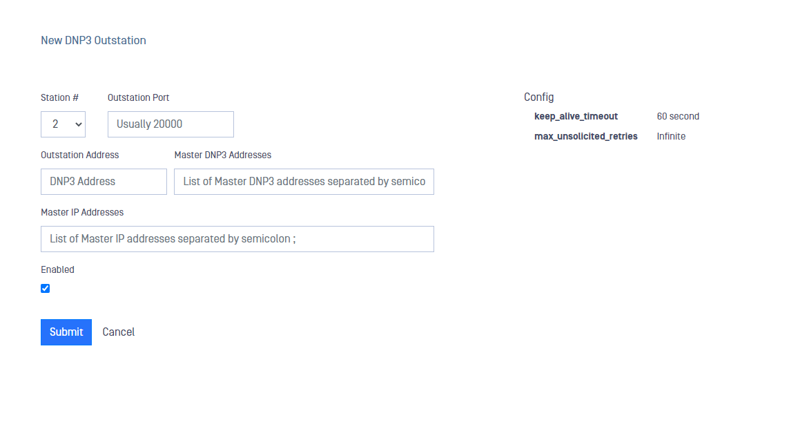
Go to DNP3 menu deploy Action button and select Add Outstation.
Type values in the following boxes:
Station #: Is similar to the Channel concept in other connectors or streams. Station # needs to be the same in both sides, RED and BLUE.
Outstation Port: DNP3 port where the Outstation is configured to listen on. Default value is 20000
Outstation Address: Is the application address of the client that must match the address defined in the client configuration. This is defined as the address of the outstation. Valid values are from 1 to 65519. Outstation Address should be different than Master Address.
Master DNP3 Addresses: DNP3 address (this is not an IP) to identify the master. You can define several addresses separated by semicolon. The number of addresses must be the same as IP addresses in Master IP Addresses. If you only have one address defined here, Master IP Addresses fuield can be empty. All addresses must be unique. Valid values are from 0 to 65519.
Master IP Addresses: List of IPs corresponding to DNP3 Master. you can define several of them separated by a semicolon and the number of IP addresses needs to match with the number of addresses in Master DNP3 Addresses field.
Enabled: This checkbox should be marked to enable DNP3 connector.
Click on Submit button to save the changes.