Network Topology
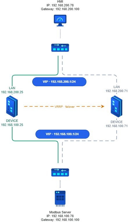
Devices Involved: HMI (192.168.200.78), Upper Switch, MDIFW-1 (Primary), MDIFW-2 (Secondary), Lower Switch, Modbus Server (192.168.100.78)
Setup:
Upper Network:
- LAN: 192.168.200.0/24
- HMI: 192.168.200.78
- Gateway: 192.168.200.100
- MDIFW-1 LAN Port: 192.168.200.25
- MDIFW-2 LAN Port: 192.168.200.71
- VIP: 192.168.200.100/24
Lower Network:
- DEVICE: 192.168.100.0/24
- Modbus Server: 192.168.100.78
- Gateway: 192.168.100.100 FW1
- MDIFW-1 DEVICE Port: 192.168.100.25
- MDIFW-2 DEVICE Port: 192.168.100.71
- VIP: 192.168.100.100/24
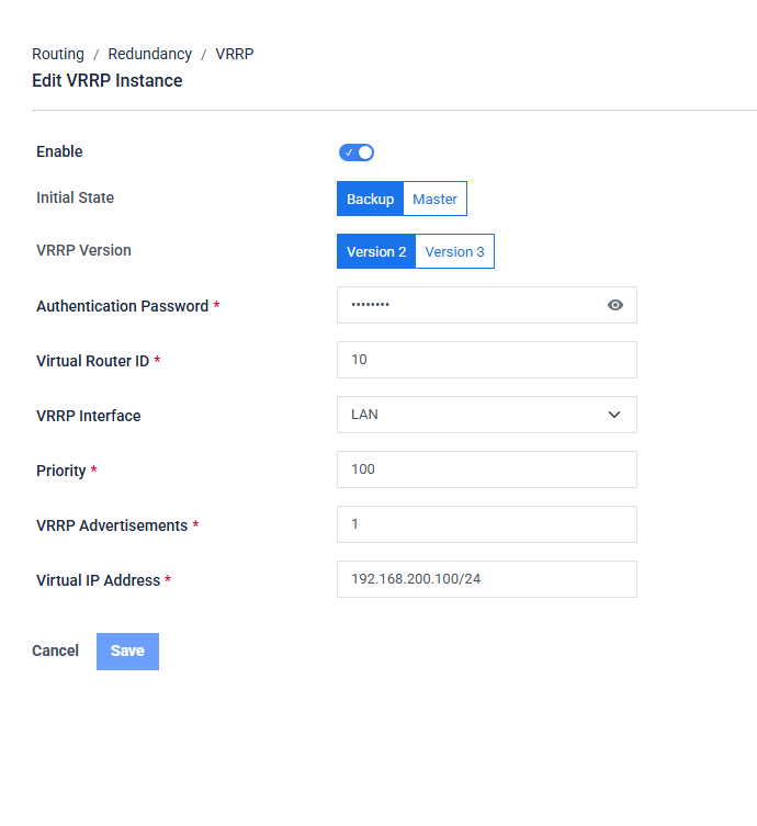
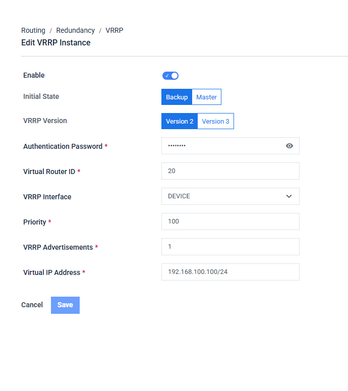
VRRP Setup 1
| UI Field | VI_10 — LAN | VI_20 — DEVICE |
|---|---|---|
| Enable | ON | ON |
| Initial State | Backup | Backup |
| VRRP Version | Version 2 | Version 2 |
| Authentication Password | 12345678 | 12345678 |
| Virtual Router ID | 10 | 20 |
| VRRP Interface | LAN | DEVICE |
| Priority | 100 | 100 |
| VRRP Advertisements | 1 | 1 |
| Virtual IP Address | 192.168.200.100/24 | 192.168.100.100/24 |
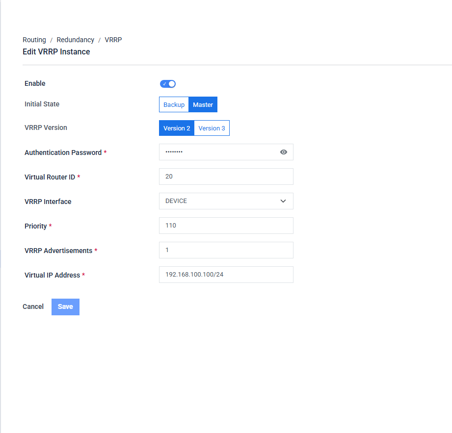
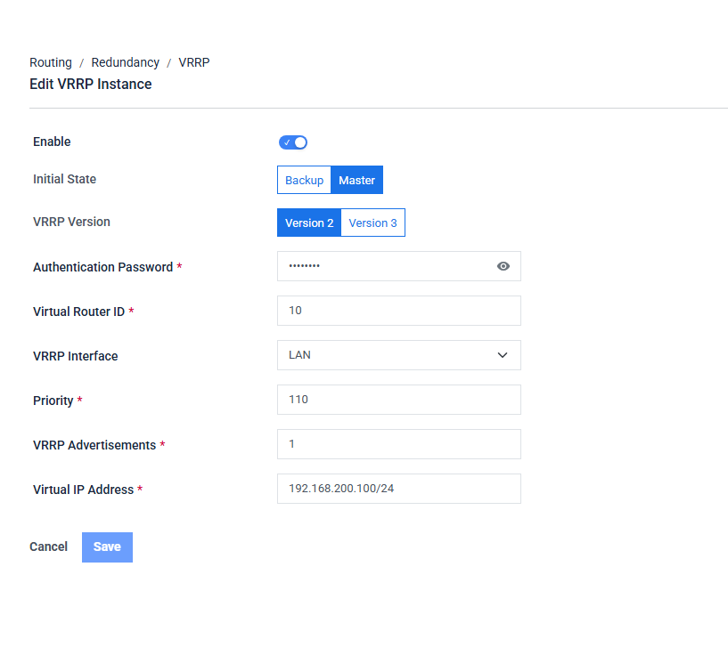
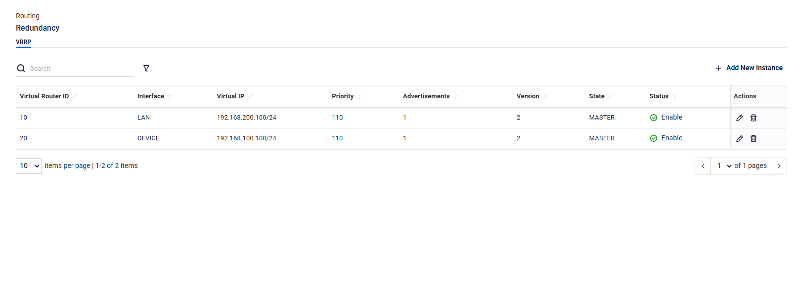
VRRP Setup 2
| UI Field | VI_10 — LAN | VI_20 — DEVICE |
|---|---|---|
| Enable | ON | ON |
| Initial State | Master | Master |
| VRRP Version | Version 2 | Version 2 |
| Authentication Password | 12345678 | 12345678 |
| Virtual Router ID | 10 | 20 |
| VRRP Interface | LAN | DEVICE |
| Priority | 110 | 110 |
| VRRP Advertisements | 1 | 1 |
| Virtual IP Address | 192.168.200.100/24 | 192.168.100.100/24 |
Benefits
Secure Cross-Network Access:
- The Modbus Server remains hidden from direct HMI access, reducing the attack surface. All communication between upper Network and lower Network passes through the Industrial Firewall, ensuring traffic is inspected and controlled at all times.
High Availability:
- VRRP ensures continuous network operation. If FW1 fails, FW2 automatically takes over both VIPs within approximately 3 seconds, with no manual intervention and no configuration changes required on the HMI or Modbus Server.
Compatibility:
- Allows legacy Modbus devices to communicate with modern HMI systems on separate networks without altering their existing configurations. The firewall handles all routing and protocol bridging transparently.
Practical Use Cases:
- An HMI in upper Network can fetch data or issue commands to the Modbus Server in Network B securely through the firewall. Modbus Server data can be monitored in real time without exposing the DEVICE network to the broader LAN.
Configuration Steps
VRRP Setup 1 : MDIFW 1 — 192.168.1.25 (MASTER):
VRRP Setup 2: MDIFW 2— 192.168.1.152 (BACKUP):
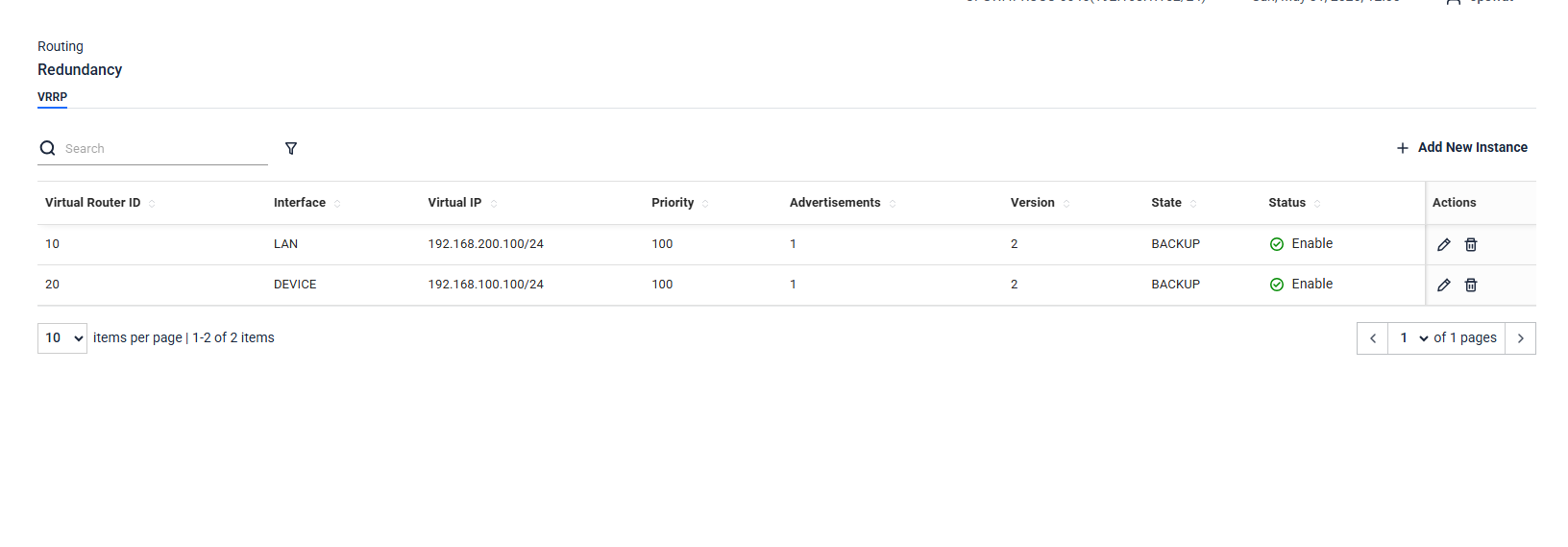
Analyze
- HMI pings LAN VIP (192.168.200.100).
- Modbus Server pings LAN VIP (192.168.200.100).
- HMI pings DEVICE VIP (192.168.100.100).
- Modbus Server pings DEVICE VIP (192.168.100.100).
- On Failover (MDIFW-1 down) MDIFW-2 detects missed VRRP advertisements after ~3 seconds and promotes itself to MASTER. All subsequent pings from HMI and Modbus Server are answered by MDIFW-2 with no configuration changes required on either device. Both VIPs remain reachable throughout the failover
VRRP does not sync Firewall Rules between MDIFW-1 and MDIFW-2. Each firewall must be configured with identical rules manually. If MDIFW-1 has rules that MDIFW-2 does not, traffic that was permitted through MDIFW-1 may be blocked after failover.
When failover occurs, it takes time for the network to update routing and ARP tables. During this window (typically 3–5 seconds), traffic may be interrupted until FW2 fully assumes the MASTER role and the virtual MAC is propagated across both switches.