Introduction
The NetWall OPC Connector allows you to configure an OPC client and OPC server to transfer OPC DA and A&E data across NetWall product family (Optical Diode, Unidirectional and Bilateral Security Gateways).
An OPC client collects data from one or more customer-owned OPC DA or A&E servers in the NetWall BLUE zone (source servers) and provides a unidirectional transfer of that data to the OPC server in the NetWall RED zone. Customer-owned OPC clients in the RED zone (destination servers) connect to the OPC server to create a read-only instance of one or more replicated OPC servers in a non-secure environment.
Supported Features
The OPC Connector provides the following features:
Supports collection from multiple OPC servers
Supports data scan rates as low as 2 msec
Replicates all standard and custom OPC properties
Supports OPC browsing
Supports Deadband and individual point scan rates
Detects communications loss and reflects it across the NetWall
High Availability failover for redundant OPC DA servers and flanking servers.
Deployment
The OPC Connector is installed on a separate flanking servers from the NetWall BLUE and RED nodes in one of the following deployments:
Installation on the same machine as a customer-owned OPC server. Additional communication software is not needed.
Installation on a separate machine from a customer OPC server. DCOM is used to allow the servers and clients to communicate.
The machines where the OPC connector software is installed are referred to as the BLUE and RED flanking servers, respectively.
For either deployment, installing the OPC Connector software creates a OPC client on the BLUE flanking server and a OPC server on the RED flanking server.
The NetWall BLUE and RED zones can have different deployments. For example, the OPC client could be on the same machine as a customer-owned server in the BLUE zone, and the OPC server could be on a different machine than the customer-owned server in the RED zone.
Each OPC Connector installation creates an OPC instance. Multiple instances can be configured on the same machine, differing by the NetWall Port number that is entered during configuration.
The following figure shows a deployment where the OPC Connector is installed on different servers in the BLUE and RED zones.
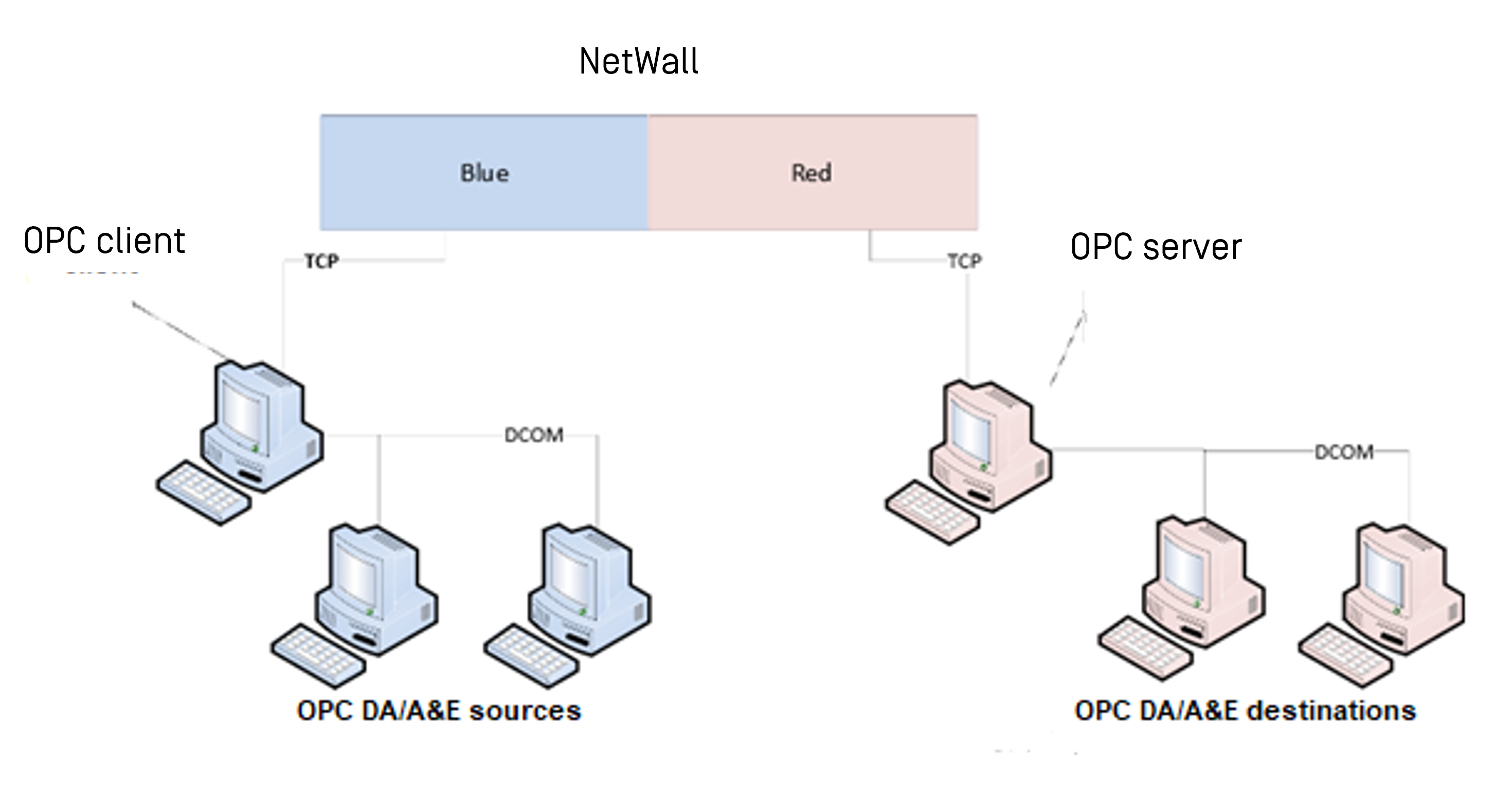
The following configuration applies:
The OPC client uses DCOM to communicate with customer-owned OPC servers (sources) in the NetWall BLUE zone.
The OPC client collects OPC data to creates a unidirectional TCP stream and sends the stream across NetWall.
The OPC server in the NetWall RED zone receives the TCP stream and replicates the OPC data.
The customer-owned OPC clients (destinations) in the RED zone use DCOM to communicate with the OPC server and read the data.
Time Stamps
The OPC Connector deviates from the OPC Foundation DA Server specifications for time stamp. According to the specification, the time stamp for an OPC value should be in relation to the OPC server that provides the Time Stamp. The OPC Connector maintains the time stamp from the OPC client. This timestamp is propagated unchanged through NetWall, to the OPC server.
Install OPC Connector
Prerequisites
You must have admin rights on any machine where you want to install the OPC Connector.
Install Microsoft NET Framework 4.5 on the BLUE and RED flanking servers.
If the OPC servers and clients are on separate machines, configure DCOM on the servers and on the customer-owned OPC clients.
Install on BLUE Flanking Server
You will receive a folder containing the .msi files shown below. Install these files on any machine in the BLUE zone where you want to create a OPC client.
Graphical Interface: OPSWAT_OPCDA_BLUE_Config_UI_Install.msi
OPC service: OPSWAT_OPCDA_BLUE_Service.msi
Update Installation
If you are updating an existing installation, halt the OPC service and uninstall the following applications, using the Windows Control Panel:
OPSWAT OPCDA BLUE Config UI
OPSWAT OPCDA BLUE Service
Install User Interface
Double-click OPSWAT_OPCDA_BLUE_Config_UI_Install.msi to open the wizard. Accept the defaults until the installation is complete.
Install OPC Service
Double click OPSWAT_OPCDA_BLUE_Service.msi to open the wizard.
Accept the defaults until you reach the Set Service Login screen. Then, select a Username that will have access to your OPC servers.
Make sure to preclude the Username with a “.\”.
Set the appropriate password. Click on OK and continue the installation, accepting the defaults until the installation is complete.
Install on RED Flanking Server
Before installing OPSWAT_OPCDA_ RED_Service.msi you need:
.NET 2.0 / .NET 3.0 feature on Windows must be enabled. Click here for some help Install .NET Framework 3.5 on Windows - .NET Framework | Microsoft Learn
OPC Core Components redistributable v3.X must be installed. Click here for more information Classic - OPC Foundation
You will receive a folder containing the .msi files shown below. Install these files on any machine in the RED zone where you want to create a OPC server.
OPC Server Wrapper: OPSWAT_OPCDA_RED_Service.msi.
Update Installation
If you are updating an existing installation, uninstall OPSWAT OPCDA RED Service, using the Windows Control panel.
Install Server Wrapper
The Server Wrapper creates the OPC Configurator, which is used to configure the OPC server on the RED flanking server.
Double-click OPSWAT_OPCDA_RED_Service.msi to open the wizard. Accept the defaults until the installation is complete.
For best operability with existing software, OPSWAT_OPCDA_RED_Service.msi has been intentionally made 32-bit. Most existing DA clients are 32-bit software. However, it is likely that some users run OPSWAT_OPCDA_RED_Service.msi on a 64-bit machine. Please check DCOM Configuration in RED side
Install OPC Client
Install your customer-owned OPC client on all computers that will communicate with the OPC server.
This chapter describes how to configure the OPC client on the BLUE flanking server to collect data from an OPC source and transmit that data across NetWall.
You must download any configuration changes made on the OPC client to the OPC service before they take effect. Refer to “Download configuration” for more information.
The general configuration process is:
Add a server: Defines an OPC source for data collection.
Add a group: Defines a container where database points from the source will be stored.
Add points to the group: Adds database points to the defined group.
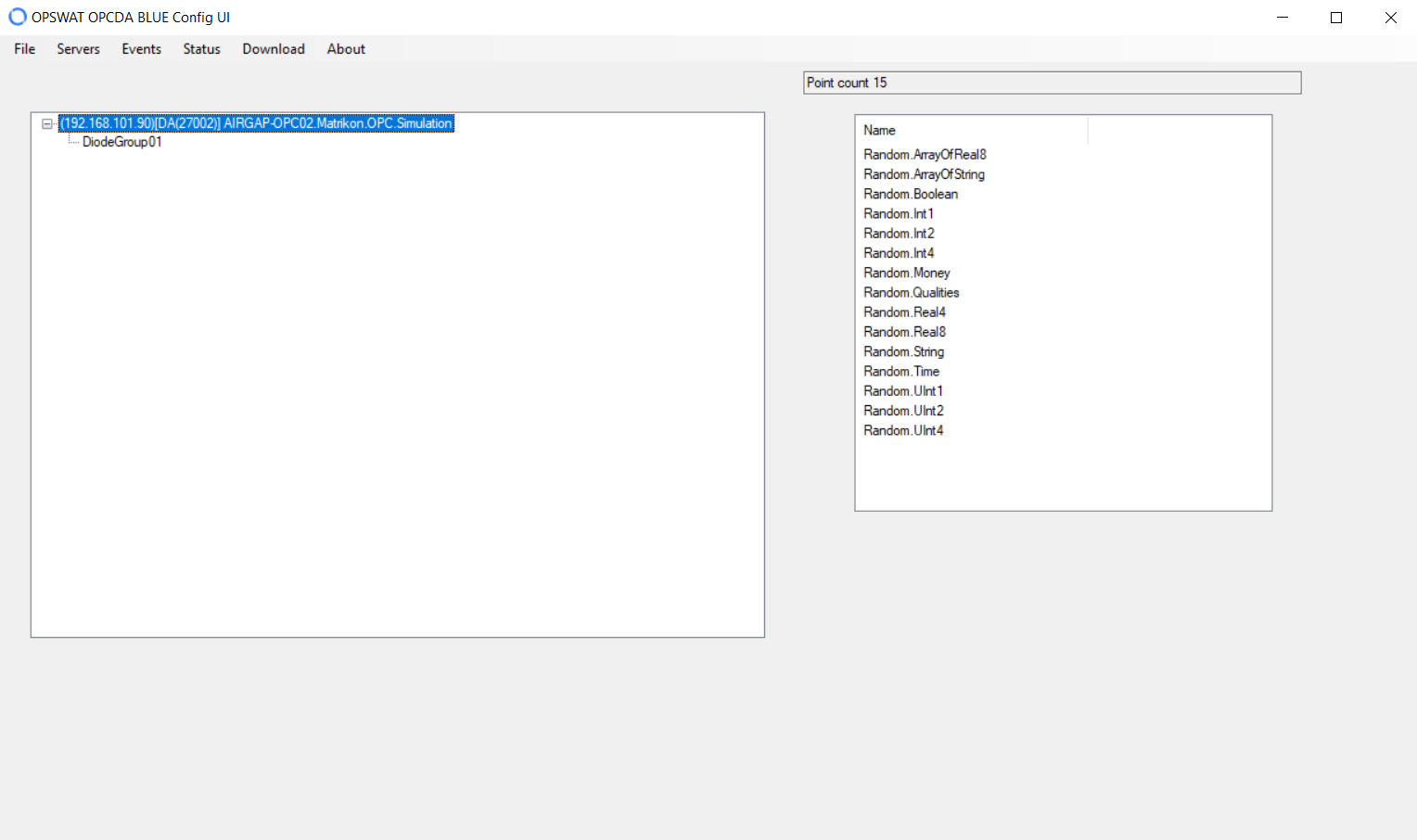
Click the OPC icon on the OPC client. The OPC Main Form pane displays.
Configure OPC Client
This section describes how to configure the OPSWAT NetWall OPC client on the BLUE flanking server to collect data from an OPC source and transmit that data across NetWall.
You must download any configuration changes made on the OPC client to the OPC service before they take effect. Refer to “Download configuration” for more information.
The general configuration process is:
Add a Server: Defines an OPC source for data collection.
Add a Group: Defines a container where database points from the source will be stored.
Add Points to the Group: Adds database points to the defined group.
Click the OPC icon on the OPSWAT OPC client. The OPC Main Form pane displays.
Backup or Restore Configuration
We recommend you back up your current configuration before making any modifications.
Select Backup/Restore from the File menu.
Add Server
This procedure describes how to add an OPC source server to the data collection.
Select Add Server from the Servers menu. The Select OPC Server pane displays. $plugin[46abjlxpbbf]
Select the type of server you want to install from the dropdown list.
Click Browse for Servers to locate available customer-owned servers of the selected type. Local Servers (OPC servers on the same machine as the OPC client) and Local Network servers (OPC servers on different machines in the same network) display. $plugin[upqb01mc3sx]
Expand a node on the local network to show OPC servers that are accessible on different machines on that network. If a node turns red when you try to expand it, OPC servers are not available. If the node turns green, OPC servers are available, and a list of the servers displays. $plugin[1opjhb8fnde]
Click the server you want to add. $plugin[9lznogwpll7]
Type the following values:
NetWall IP address: NetWall BLUE IP address
NetWall Port Number: TCP port number that was allocated for OPC during streaming configuration. Refer to the NetW__all User Guide for more information.
Click the OK button.
Select another server and repeat step 6 for each source you want to add to the data collection. The servers will display on the OPC Main Form.
Configure Remote Server
You can add remote OPC servers to your local network. Right-click Local Network to display the configuration menu.
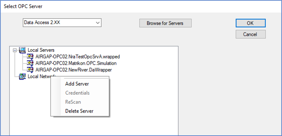
Add Remote Server
Select Add Server to add a server to your local network. A popup displays.
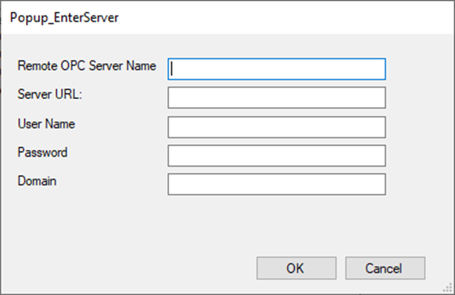
Type the server information and click OK. The server displays in the Local Network list.
Edit Remote Server
Select Credentials to edit the server. The popup shown in Add remote server displays. Edit the settings as necessary and click OK.
ReScan
Select ReScan to re-examine the network for OPC servers. Any new servers that are located during the scan are displayed in the list.
Delete Remote Server
Select Delete Server to remove the server from your local network.
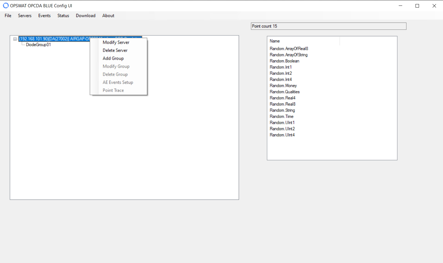
Modify or Delete Server
To change the server IP address or port number or delete the server, right-click the server on the OPC Main Form and select Modify Server or Delete Server, respectively.
Add Group
This procedure describes how to add a group to an OPC source server. A group defines the data collection parameters for the database points that will be added.
Right-click the OPC server on the OPC Main Form and select Add Group. The AddGroup pane displays. $plugin[vnkg2n6l0vj]
Enter the following information:
Name: Name for the group
Active: Click to allow data to be collected for the group.
Update Rate: Click to use Asynchronous Notification (OPC Server Data Callback). The box is selected by default. If selected, the OPC server pushes data to the OPC Service for this group whenever data changes, based on the Update Rate.
Select the maximum update rate your group will support for Data Callback. The default is 1000ms. If this rate is not set correctly, data loss can occur. For example, if the OPC server processes values at 250ms and you set the Update Rate to 1000ms, you will only receive every 4th change from the OPC server.
Polling Rate: Click to use Synchronous Polling. This value sets the rate at which group values are polled from the OPC source. Synchronous Polling can be used in addition to Data Callback.
Keep Alive Rate: Keep-alive time for a subscription to cause the server to provide client callbacks on the subscription when there are no new events to report.
Deadband OPC: Percent change in an item value that will cause a subscription callback for that value to a client. This option only applies to items in the group that have a numeric value (as opposed to a state) and is only valid if Update Rate is selected.
Watchdog Timer: Click the checkbox, then set the desired time in minutes. If enabled, the OPC Connector monitors activity for this group. If there is no activity for the amount of time specified, the application closes and then re-opens its connection to the specified OPC source.
Locale: Time zone for the Watchdog Timer. Click the checkbox, then select the desired time zone.
Click the OK button to add the group.
Add Points to Group
This procedure describes how to add database points to your group.
The BuildGroup pane displays after you add a new group, or you can right-click a group on the Main OPC Form and select Modify Group.
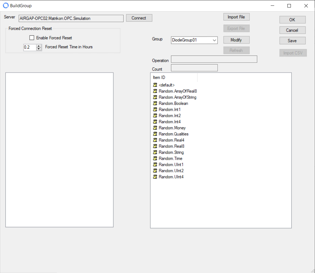
Complete the following information:
Click to Enable Forced Reset, if desired. If clicked, set the time, in hours, after which you want the OPC Connector to disconnect and reconnect. When the time elapses, the OPC Connector disconnects from and immediately reconnects to the OPC source.
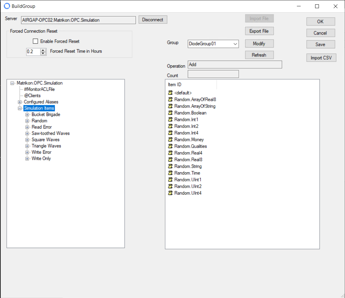
Click the Connect button to connect to the OPC source you just added. If the server supports the Browse function, the list of database points on that server displays. $plugin[f5effe31bhg]
Expand the folder on the left and click to select individual points, or select an entire folder by right-clicking the folder and selecting Select Children. If you Select Children, the OPC Connector extracts OPC attributes for each point in the selection. When completed, the selected points display in the Item ID pane on the right. $plugin[4jbpjokv543]
Click Save to return to the OPC Main Form.
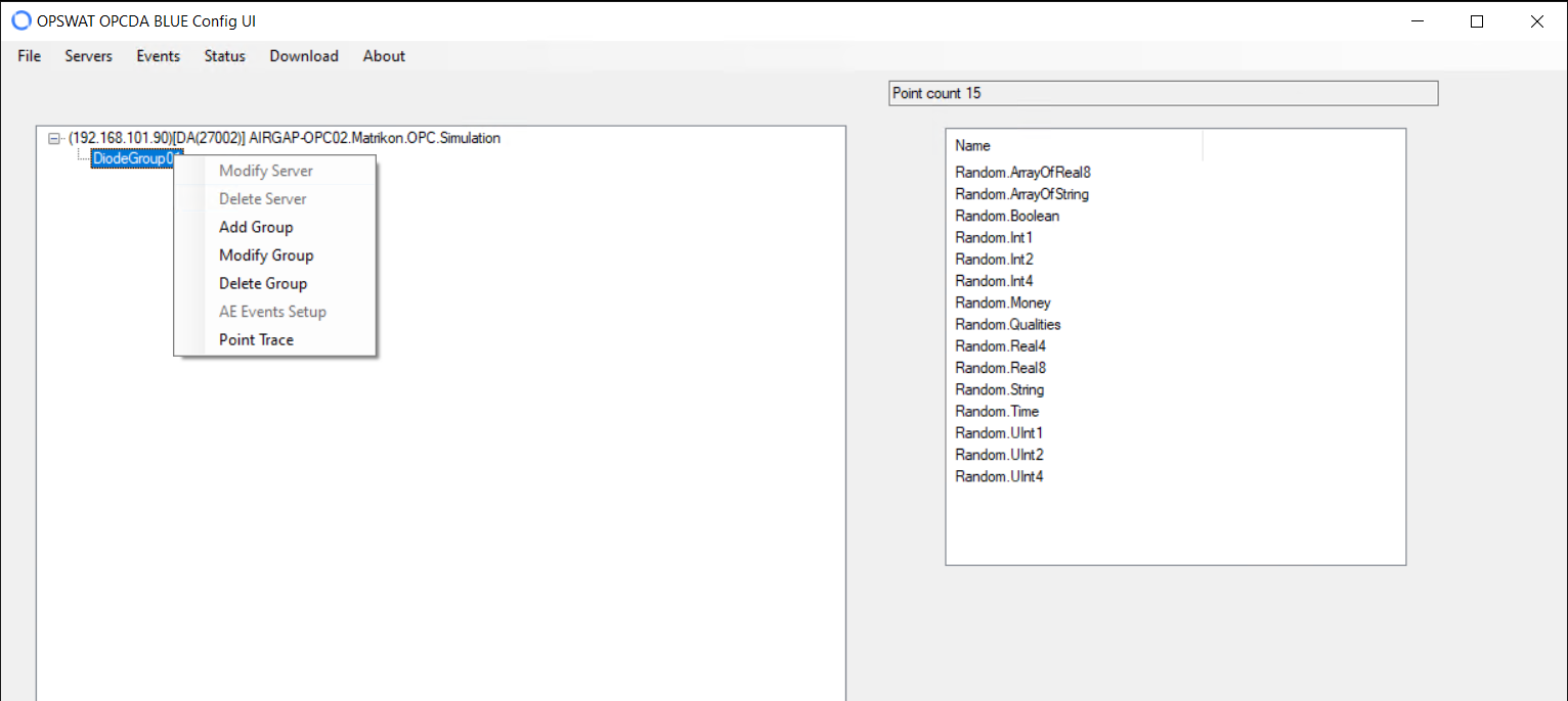
Modify Group
Click the Modify button to make changes to a group. The AddGroup pane displays, and you can edit the values. Refer to “Add group” for definitions of the values. You can also change the name of the group in the AddGroup pane to add a new group or make changes to a group other than the one selected when you opened the BuildGroup pane.
You can modify any group by right-clicking the group on the OPC Main Form and selecting Modify Group.
Refresh Group
Click the Refresh button on the BuildGroup pane to get the newest data for the group.
Import File
Instead of connecting to the OPC server and selecting each point, you can use buttons on the BuildGroup pane to import a saved group as a .xml or .csv file. The contents of the file will be displayed as a group and its associated points.
Import .xml file
Click the Import File button. The C:\ProgramData\OPSWAT\XmlExport directory displays.
Browse to locate the .xml file.
Select the file and click Open. The contents of the file will merge with the current window content as a group and its points.
Import .csv file
A .csv file is generally created by hand, separately from the OPC connector. This file can contain detailed information and attributes on the points in a group.
Click the Connect button. After the server connects, the Import CSV button becomes active.
Click the Import CSV button. The CSV Import pane displays.
Click the Search button to locate the .csv file.
Click the OK button to import the file. The import status displays in the Status bar. Any errors in import display in the Errors section.
When the import is complete, the contents of the .csv file merge as a group, points, and attributes with the contents of the BuildGroup pane.
Export File
You can export a group from an OPC server as an .xml file and then import that file to a different OPC server.
Click the Connect button. After the server connects, the Export File button becomes active.
Click the Export File button. The C:\ProgramData\OPSWAT\XmlExport directory displays.
Enter a name for the .xml file and click OK to create the file.
Edit Points
There are two ways to edit points in a group:
Right-click a point in the BuildGroup pane and select a value from the menu. $plugin[20ma1uisitt]
Double-click a point on the OPC Main Form and click a button in the resulting menu. $plugin[iprbamhm3f6]
You can perform the same tasks from either menu.
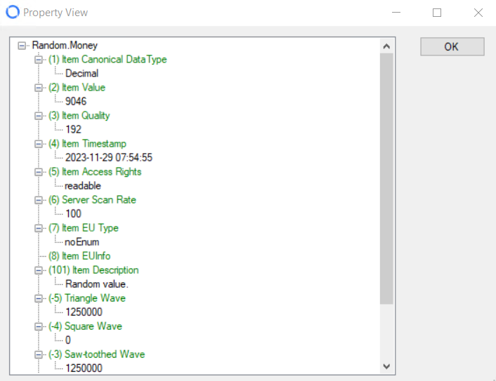
View Properties
Select View Properties or View to display properties for the selected point. Properties are specific to the OPC source.
Delete Point
Select Delete to delete the selected point from the group.
Trace
Tracing monitors all transactions for a selected point. Whenever the value of the point changes, the following is logged:
Time of the change
New value of the point
Point status
Select Trace to display the TraceEnable pane.
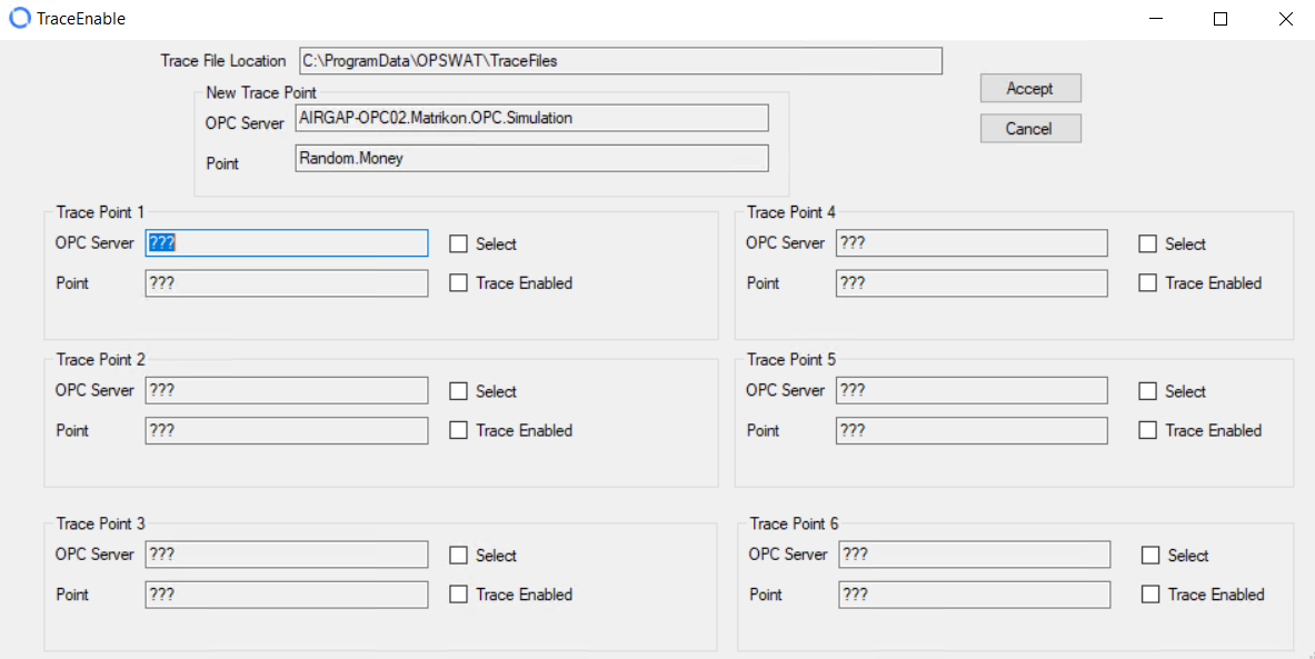
Click Select for the Trace Point 1-6 that you want to use.
Click Trace Enabled to enable trace for that point.
Click Accept to accept your changes.
After approximately 15 seconds, point values for the point being traced display in the Trace Log, located in C:\ProgramData\NraOPC\TraceFiles. An entry is logged into the Trace Files when the selected point is updated from either a Poll command or a Data Event Callback.
The TraceFiles folder is not created until actual values exist for the point being traced.
Each line of Trace data displays as follows:
12/01 07:13:03.266 SVR320-DEVOPC.NraTestOpcServer.NET.DaServer.Wrapped,Dynamic/Analog Types/dbt0003,22.3849607955237,Good,DataChange
The data sampling time is registered to the Millisecond level. The last field (DataChange) gives the origin of the data. DataChange is data from a Data Event Callback or Asynchronous Data. Poll would represent data from a Synchronous Poll issued by the OPC Connector.
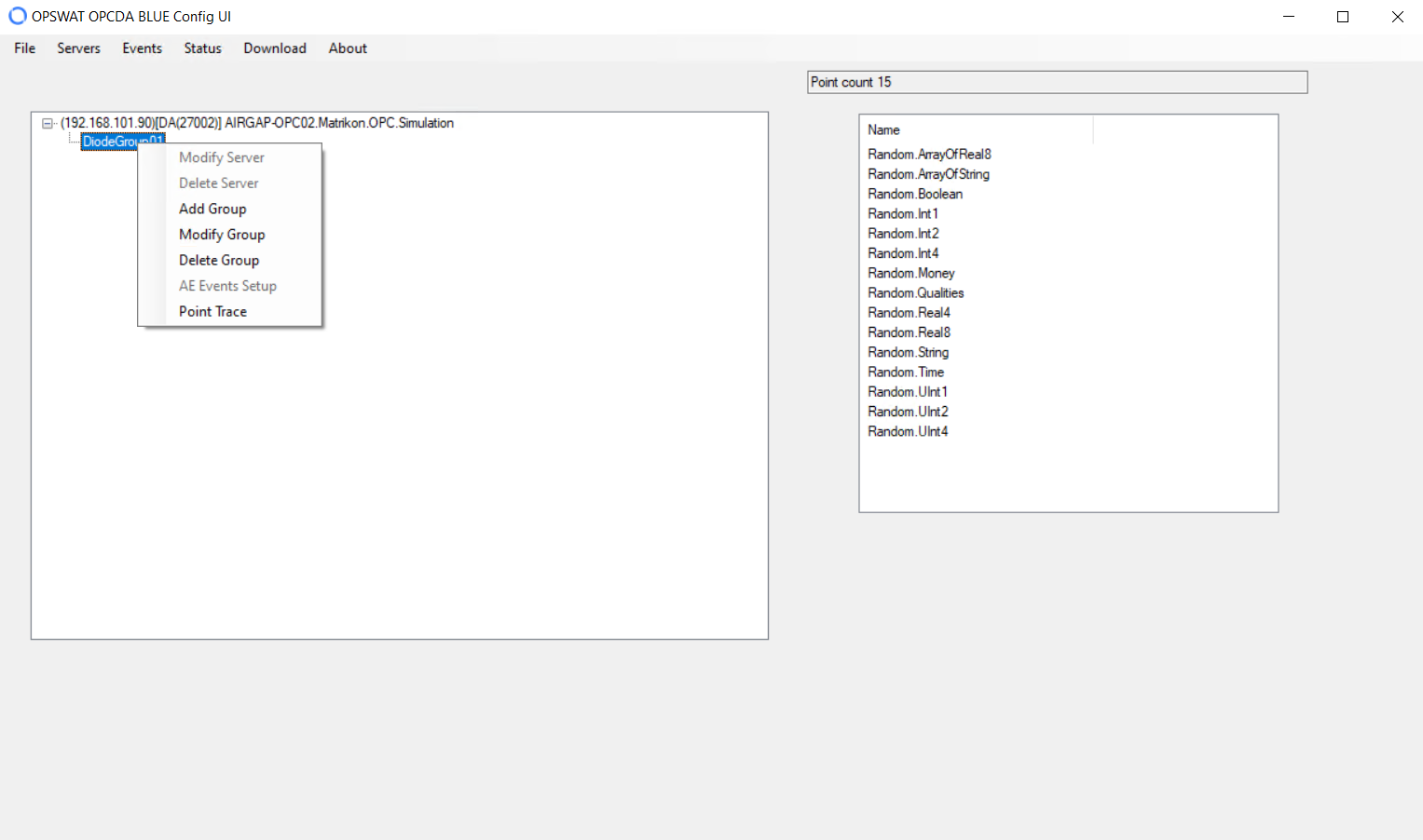
To view all traces configured for a group, right-click the group on the OPC Main Form and select Point Trace.
OPC Main Form and select Point Trace.
Edit
Select Edit to change the default attributes of the point. The Edit Items pane displays.
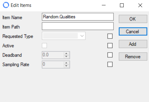
You can type new values for Item Name or Item Path. For all other boxes, you must click the checkbox before you can edit the values.
Requested Type: Possible OPC values for that point
Active: Click to enable or disable data collection for the point
Deadband: Percent change in an item value that will cause a subscription callback for that value to a client. This parameter only applies to items in the group that have a numeric value and is only valid if Data Callback is selected.
Sampling Rate: Polling rate for that point
Click the OK button to save your changes.
Complex Item
To view a complex item (if available on your OPC server):
Right-click the group that contains the item on the OPC Main Form.
Select Modify Group. The BuildGroup pane displays.
Click the Connect button.
Right-click the item on the left side of the BuildGroup pane and select View Complex Item.

Delete a Group
To delete a group, right-click the group on the OPC Main Form and select Delete Group. Click Yes to confirm your action.
OPC DA BLUE Flanker Redundancy
The NetWall OPC DA Connector supports redundant OPC DA flankers on Blue. One flanker is deemed Primary. The primary flanker will always be the flanker in control if both flankers are operational. If the Primary flanker fails, the Secondary flanker assumes control. When the Primary flanker becomes available, the Secondary flanker relinquishes control, and the Primary flanker assumes control.
The Secondary flanker receives the OPC DA Server configuration from the Primary Flanker. The OPC DA Server configuration cannot be modified by the Secondary Flanker. Server Configuration can only be done by the Primary Flanker.
The Redundant OPC DA flankers communicate with each other via TCP/IP.
Configure Primary OPC DA Flanker for Redundancy
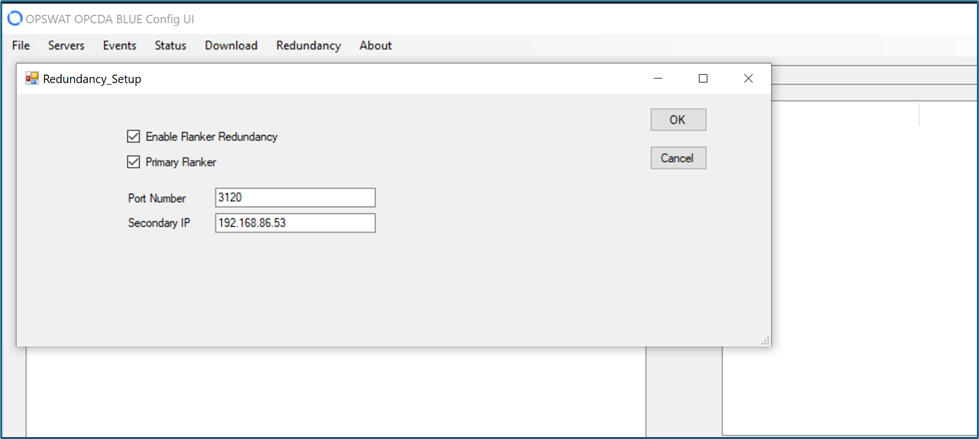
Login into OPC DA BLUE Config UI and select Redundancy from the top menu.
Type values in the following boxes:
Enable Flanker Redundancy: Tick checkbox to enable/disable Flanker Redundancy.
Primary Flanker: Tick checkbox to designate as the primary Flanker
Port Number: Port number to use for TCP communication between Primary and Secondary flankers.
Secondary IP: - IP Address of the Secondary Flanker. Either the IP Address or the Host name of the Secondary Flanker can be used.
Click on OK button to save the changes.
Configure Secondary OPC DA Flanker for Redundancy
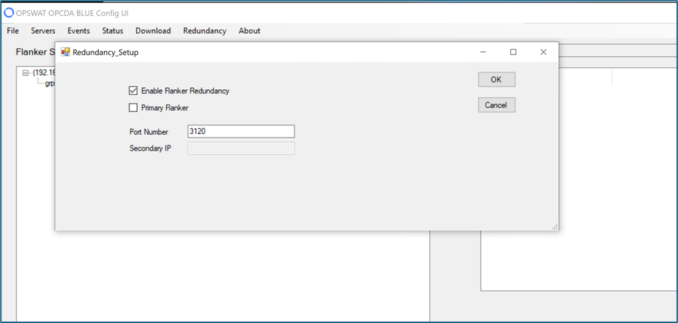
Login into OPC DA BLUE Config UI and select Redundancy from the top menu.
Type values in the following boxes:
Enable Flanker Redundancy: Tick checkbox to enable/disable Redundancy
Primary Flanker: Checkbox to designate the Primary Blue Flanker (unchecked for Secondary)
Port Number: Port number to use for TCP communication between Primary and Secondary flankers.
Secondary IP: IP Address of the Secondary Flanker. No value needed for the Secondary Flanker configuration. It is defined by the primary.
Click on OK button to save the changes.
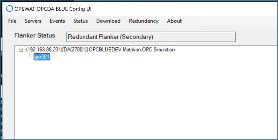
View Flanker Configuration Status
Once configured, the Home screen will display the configuration of the Flanker (Primary Flanker or Redundant Flanker).
Primary Flanker Redundancy Status
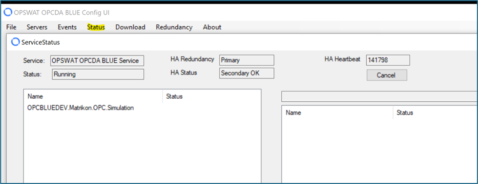
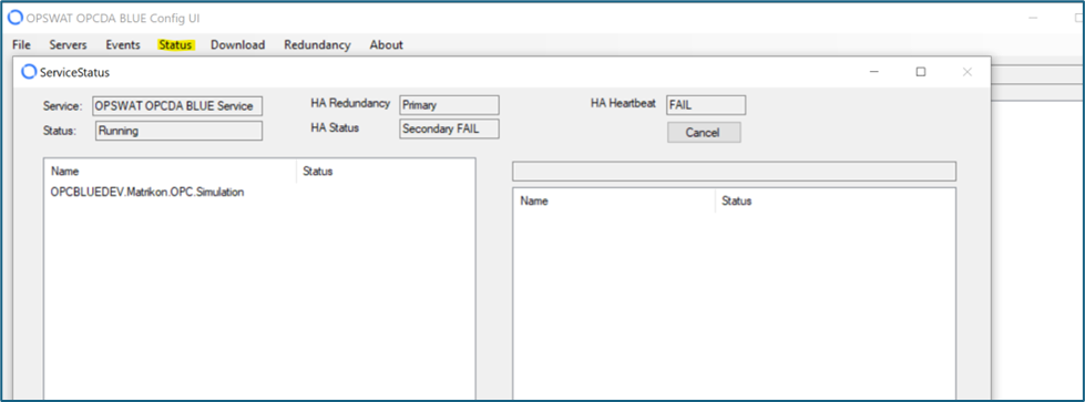
Select Status on the Home screen on the Primary Flanker to view the current status of redundancy.
In the example below, the Secondary Flanker is operational. The HA Heartbeat is a message that is sent from the Primary to the Secondary Flanker, telling the Secondary Flanker that the Primary is operational.
If the Primary Flanker is unable to communicate with the Secondary Flanker ,the display will look as follows:
Secondary Flanker Redundancy Status
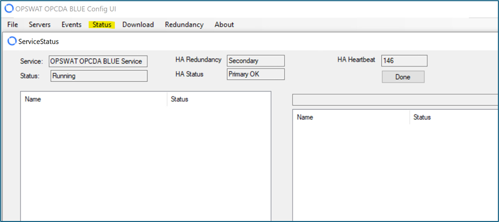
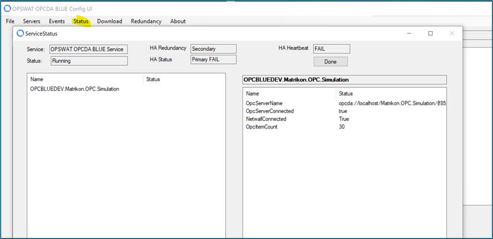
Select Status on the Home screen on the Secondary Flanker to view the current status of redundancy.
In the example below, the Primary Flanker is operational. The HA Heartbeat is a message that is sent from the Primary to the Secondary Flanker, telling the Secondary Flanker that the Primary is operational.
If the Primary Flanker is unable to communicate with the Secondary Flanker, the display will look as follows:
Windows Event Logs
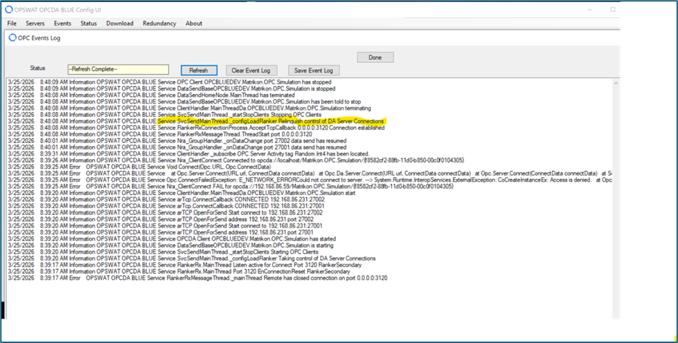
When the Secondary Flanker takes control of the OPC servers, the Windows Event Log will show that the Secondary Flanker has taken control.
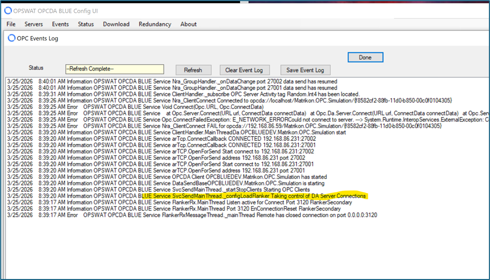
When the Primary Flanker becomes available, the Windows Event Log will show that the Secondary Flanker is relinquishing control of the OPC DA servers.
OPC DA Server Redundancy
The NetWall OPC DA connector can specify redundant OPC DA Servers. The following conditions must be met for redundant OPC DA Servers:
The schema for both OPC DA Servers must be identical
The Flanker must have DCOM access to both OPC DA Servers
If redundant flankers are implemented, both flankers must have DCOM access to the OPC DA Servers.
There is no Primary server in a redundant OPC DA Server pair. The Blue Flanker will attempt to connect to one of the pair members, and it will stay with that member as long as it is successful in collecting data from that member.
There is no specific configuration on Red for Redundant OPC DA Servers. If two ports are specified for a given Blue OPC DA Server (see next section), then two Red Flankers can be configured. Each Red Flanker will receive the same Blue Schema/Data, and each Red Flanker will have live data available.
Configuring an OPC DA Server for Redundancy
Login into OPC DA BLUE Config UI and select Severs from the top menu.
Select an OPC DA Server
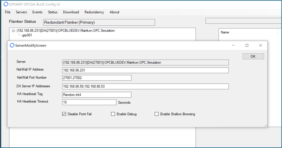
Type values in the following boxes:
Server: OPC DA server selected for redundant configuration.
NetWall IP: Address of the NetWall BLUE machine.
Port Numbers: Port Numbers that the Blue Flanker will use for its NetWall connection. Up to two port numbers can be specified. If two port numbers are specified, the OPC DA data/schema transmissions will be replicated on the second port.
DA Server IP Address: With redundant DA servers, we specify the IP address of each server. The IP Address that appears first will always be the first server that the Flanker will attempt to connect to.
HA Heartbeat Tag: Name of a tag in the OPC server. The tag can be any valid type (INT, FLOAT, etc.). When present, the Blue Flanker will monitor this tag for changes in value. If the value of the tag does not change within the timeframe specified in the HA Heartbeat Timeout field, the Blue Flanker code will switch to the opposing OPC Server.
Disable Point Fail: Under normal circumstances, the Blue Flanker will set the status of all OPC points to FAIL if it is unable to process values from an OPC Server. Selecting this box will prevent the Blue Flanker from failing all OPC Points.
Enable Debug: When selected, this causes a large amount of debugging information to be placed into the Windows Event Log for the OPC Server. This normally is left unchecked.
Enable Shallow Browsing: When selected, the Blue Flanker will only collect minimal required attributes (tag name, value type, value status) from the OPC server. It will not browse for attributes on the OPC Server.
Click on OK button to save the changes.
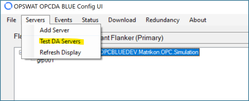
Testing OPC Servers
OPC Da Server testing can be performed on both the Primary and Secondary Flanker. If redundant OPC Servers are present, both OPC Servers will be tested. The testing procedure can be performed from the Secondary Blue Flanker as well, if redundancy is enabled.
Configure A&E Server
If you add an A&E OPC server, you can configure an Events subscription from the OPC Main Form. Creating a subscription lets you monitor events specific to the A&E server.
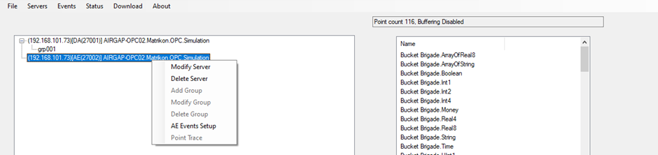
Right-click the server and select AE Events Setup. A browse pane displays. $plugin[5ekjlsbz9z0]
Click the Connect button to connect to the selected server or use the Browse button to locate and then connect to a different server.
Click <new subscription> to create a new subscription. A popup displays. $plugin[enfjssbaxmq]
Enter a name and click OK. A Create Subscription pane displays. $plugin[ngo7erj8jde]
Select the Categories of events you want the subscription to track. All Attributes display on the right side of the pane and depend on the configuration of your A&E server.
Select the type of filters you want the subscription to run and enter High and Low Severity values.
Click Next to display the Qualified Name and Node Type for your OPC A&E server.
Click Done to create the subscription.
Configure Subscription
Click the name of the subscription on the Browse pane to display a menu that allows you to test, modify, or delete the subscription.
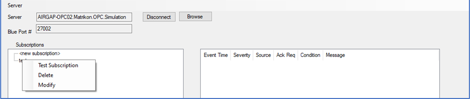
Select Test Subscription to run the subscription and pick up any A&E events.
Select Delete to delete the subscription immediately.
Select Modify to change the subscription parameters.
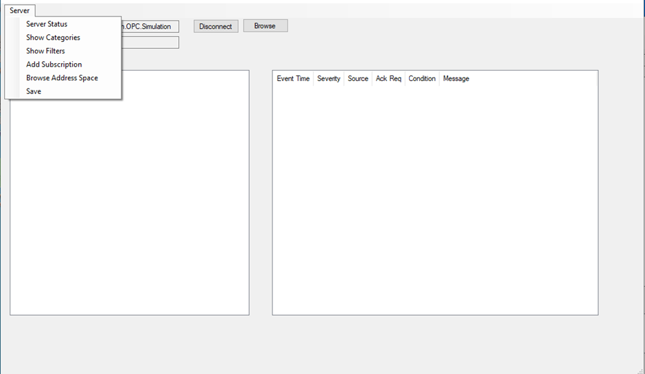
View A&E Server Information
After connecting to the A&E server, you can view server information from the Browse pane. Click the Server menu to display the options.
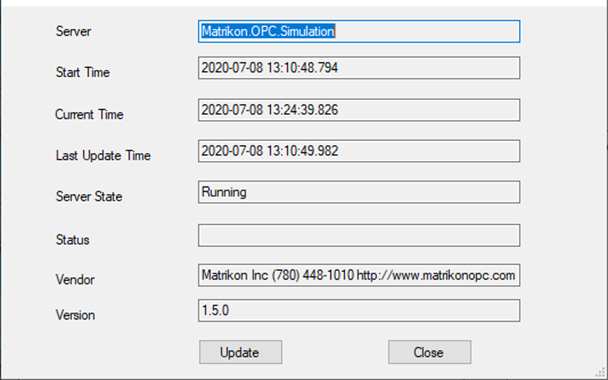
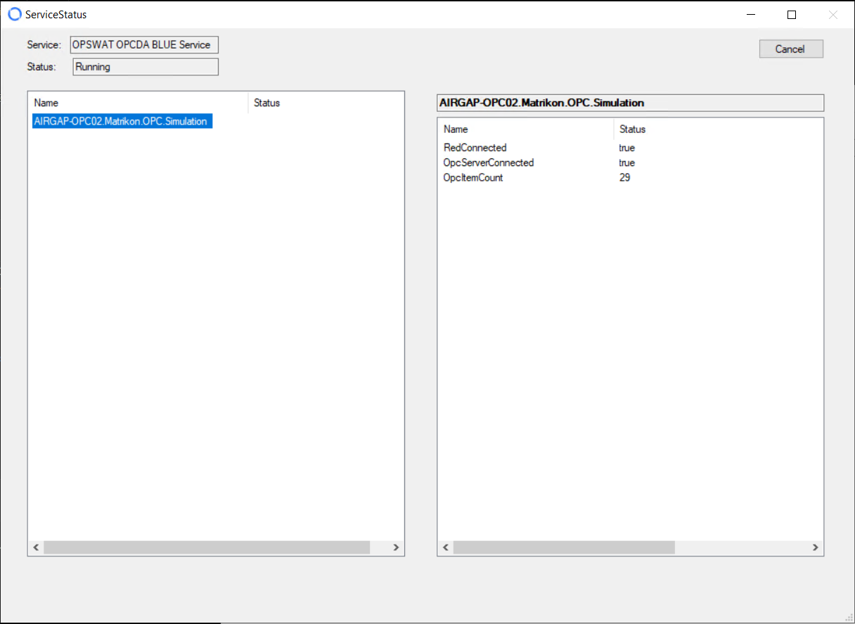
Server Status
Select Server Status to view information about the server. A display pane opens.
The screen shows:
Start , Current, Update Time: Time that the OPC A&E server was Startes, Current and Update time.
Server State: Show that the server is running
Status: Status of data being passed by the server.
Vendor: OPC A&E Server Vendor
Version: Version of OPC A&E server.
Update: Click the Update button to refresh the information.
Show Categories
Show Categories
Select Server Categories to display the categories that were selected for the subscription.
Show Filters
Select Show Filters to displays filters that were selected for the subscription.
Add Subscription
Select Add Subscription to go to the <new_subscription> option and add a subscription to the A&E server.
Browse Address Space
Select Browse Address Space to go to the address space for the A&E server and see if there are other A&E servers on the network.
Save
Select Save to save any changes you made to the subscription.

Test Connectivity
The OPC Connector contains a built-in test client. You can use this client to verify connectivity to a server.
Select Test DA Servers from the Servers menu on the OPC Main Form. OPC sources and their associated groups display on the left. If the server name is green, the test client could connect to the server. If the server name is red, the test client could not connect to the server. $plugin[tuuqgqth4er]
Click on a group to start collecting data from that group. You can click different groups and servers. Values display in the panel on the right. $plugin[y3l9003w65w]
Click the Done button when finished.
Download Configuration
You must download all configuration changes on the OPC client to the OPC service before the changes take effect.
The OPC service (BshoreOPCTxSvc) is a Windows service that runs unattended on the OPC client. This service collects data from the specified OPC sources and sends that data across NetWall.
If the service is not running, the Status and Download menus are greyed out on the OPC Main Form. When the service is running, select Download Config to OPC TX Service from the Download menu. An Update Server pane displays.
Click Yes to send the configuration to the service. The download status displays on the OPC Main Form.
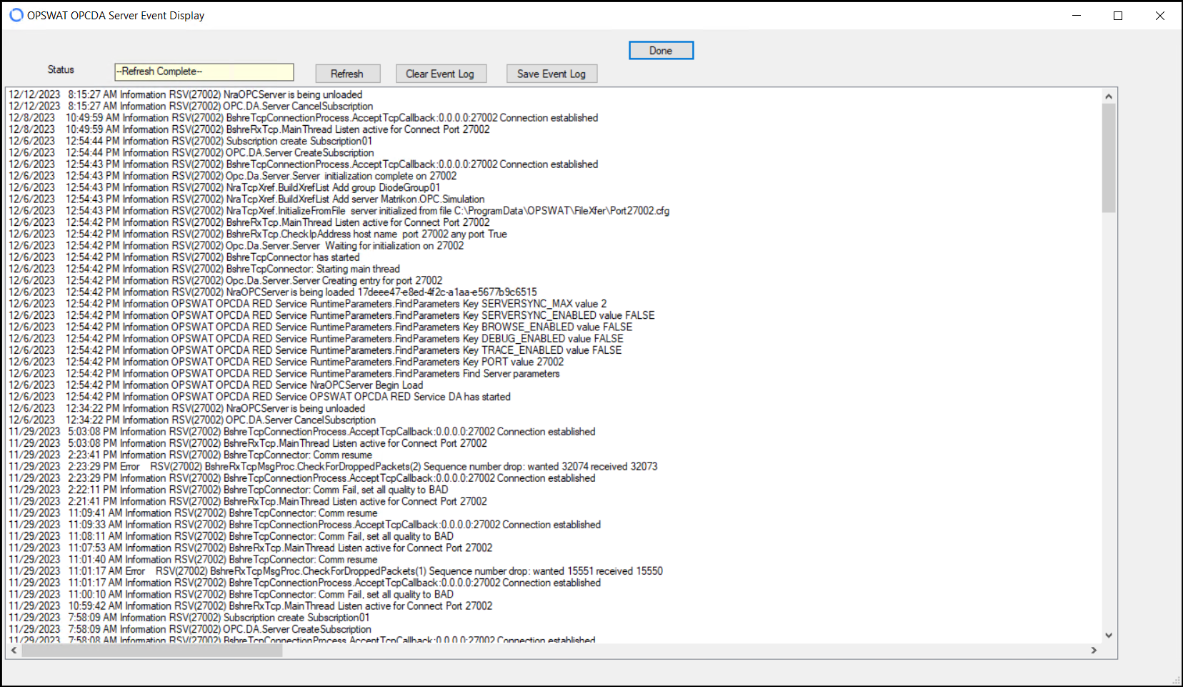
View Client Events
Click Events on the OPC Main Form to view events on the OPC client. The Events log displays.
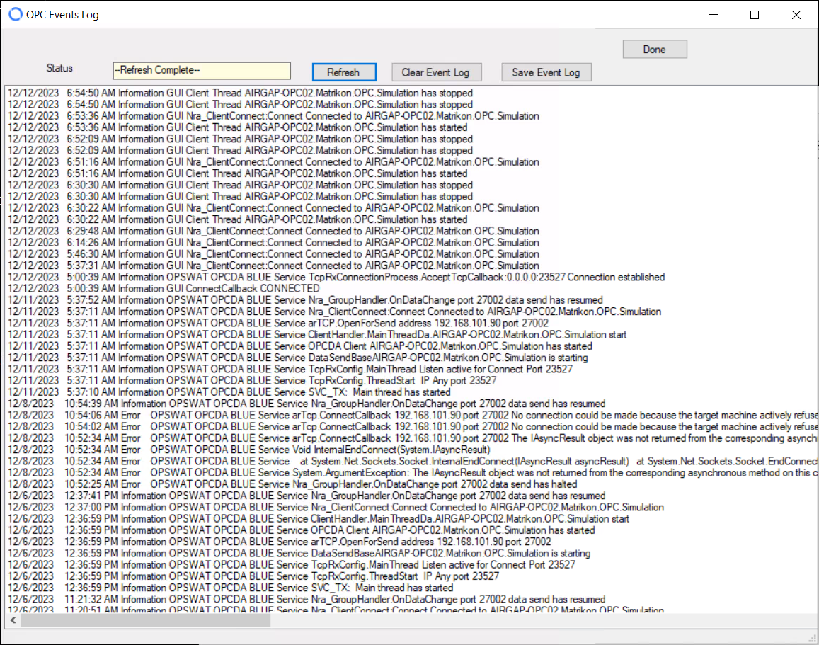
Use the appropriate buttons to Refresh, Clear, or Save the event log. Click the Done button to exit the log.
View Connection Status
Click Status on the OPC Main Form to display the status of the OPC connection.
Click on an OPC source to display the status of the OPC connection and the current number of values received for the last 2-second interval.
Configure OPSWAT OPC Server
This section describes how to configure the OPC server on the RED flanking server to receive data sent across NetWall by the OPC client on the BLUE flanking server.
Installing the OPC Connector on the RED flanking server creates a OPC server instance. Customer-owned OPC clients (destinations) can connect to that instance to receive read-only data from OPC sources in the NetWall BLUE zone.
Multiple instances can be created, differing in the NetWall Port Number where each instance connects.
Click the OPC Config tool icon on the OPC server. The OPC Server Configurator displays:
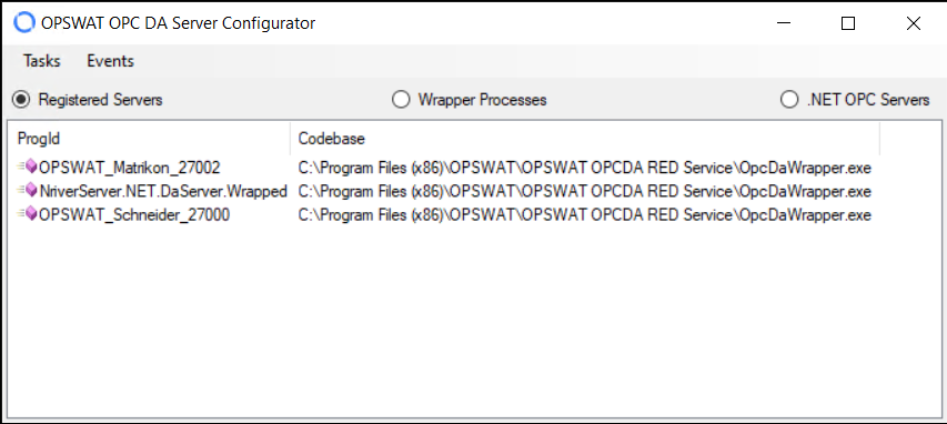
Click a radio button at the top to determine the data that displays:
Registered Servers: Servers that have been selected to receive OPC data.
Wrapper Processes: Processes installed on the RED flanking server by the Server Wrapper
.NET OPC Servers: OPC servers that are available to be registered
Add Server
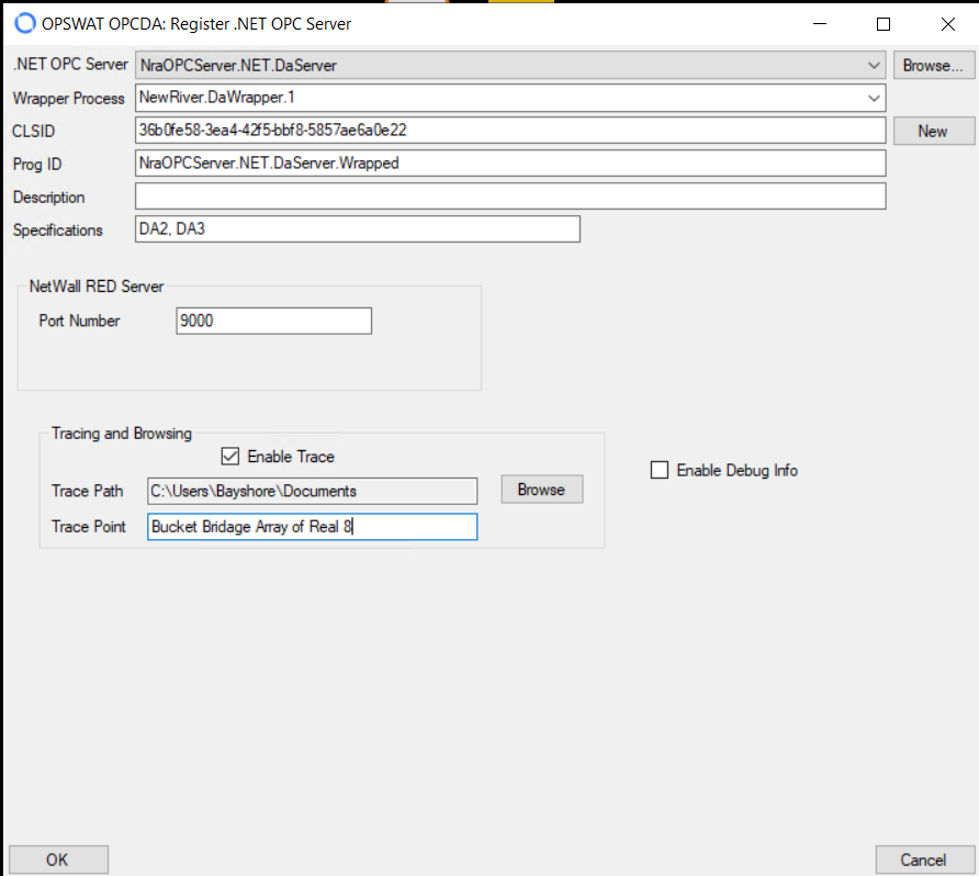
Select Register Server from the Tasks menu. The Register .NET OPC Server pane displays. $plugin[bijvik25dgb]
Type information in the following boxes (some boxes are auto-populated, but you can change the values):
.NET OPC Server: Select a DA or A&E server from the dropdown or click the Browse button to locate a different OPC server.
Wrapper Process: Select the appropriate wrapper for the DA or A&E server.
CLSID: Class ID. A unique identifier created automatically for every OPC server. Click the New button to generate a new Class ID.
Prog ID: Unique ID for this OPC server. Type the desired value.
Description: Meaningful description for the server
Specifications: Type of OPC server
Port Number: NetWall RED port number
Enter the Port Number for the NetWall RED server.
Click to enable Tracing if desired. Refer to “Tracing” for more information.
If you enable tracing, enter or browse to locate the Trace Path, and enter the name of the Trace Point.
Click the OK button to save the server configuration and return to the OPC Server Configurator.
Repeat this process for each instance that you want to create.
Click the Exit button to close the tool.
Tracing
Tracing can be used to monitor the OPC server for a single point.
In the following example, Enable Trace was selected, an output folder was specified, and a Trace Point was entered (Bucket Brigade Array of Real 8). You can change the Trace Point only when your OPC client is disconnected from the RED flanking server.
The output file has a .txt extension, but the values are comma separated so you can import them into a spreadsheet.
Trace output in the trace file appears as follows:
comparison list for Dynamic/Analog Types/dbt0007
Event Source Value Time Event Time Value
ValUpd 11:27:14.698 11:27:08.187 74.4310620748477
Subscr,11:27:14.698,11:27:08.193,74.4310620748477
ValUpd,11:27:14.798,11:27:08.296,76.1249282357974
Subscr,11:27:14.798,11:27:08.301,76.1249282357974
ValUpd,11:27:14.899,11:27:08.387,77.7785116509801
Subscr,11:27:14.899,11:27:08.398,77.7785116509801
ValUpd,11:27:15.001,11:27:08.492,79.3892626146237
Subscr,11:27:15.001,11:27:08.494,79.3892626146237
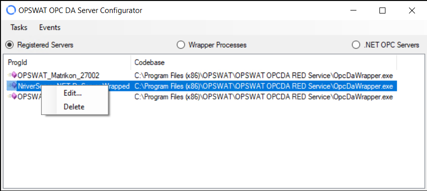
Edit or Delete Server
To edit or delete a server, right-click the server and select Edit or Delete from the menu.
Export Server
To export the server contents as a .xml file, select Export Registered Servers from the Tasks menu and browse to the desired location.
View Server Events
To view events on the OPC server, click Events on the OPC Configurator. The event log displays.
Click the appropriate button to Refresh, Clear, or Save the event log.
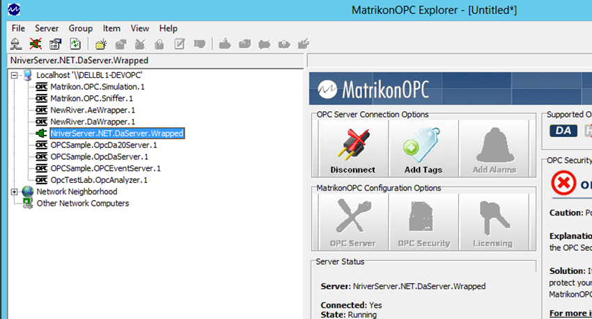
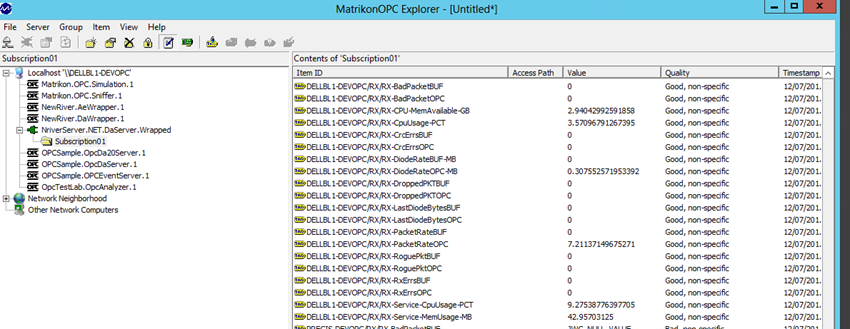
Using the Customer OPC Client
After installing the OPC Connector and configuring data collection, you can use a standard OPC client to connect to the OPC server and view the statistics for the OPC Connector as a series of OPC Points.
The following images show example output with an OPC client simulator.
DCOM Configuration on RED side
For best operability with existing software, BshoreOPCServerWrap.msi has been consciously made 32-bit as most existing DA clients are 32-bit software. However, it is likely that a user runs the BshoreOPCServerWrap.msi on a 64-bit machine. This leads to a bit of confusion, since some 32-bit DCOM servers cannot be found easily.
Check the steps to launch the 32-bit DCOM config console:
Use OPSWAT’s RED OPC configuration utility to create the DA server of your choice, in this example – we will be configuring the “OPSWAT_Schneider_ 27000” server.

Press the “Windows” button or in the Search box, type:mmc -32 (that is: mmc [space] -32). This command launches MMC in 32-bit mode. Once launched, it will bring application such as:
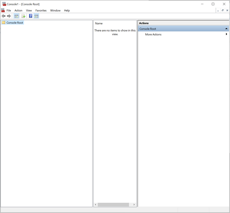
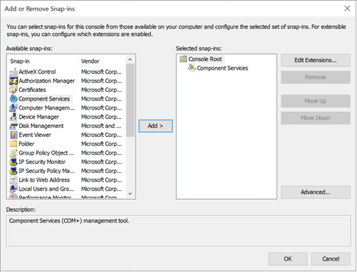
From the Menu – select “File -> Add or Remove Snap-Ins” (or press CTRL+M). Select “Component Services” and click “Add >” button.
Walk through the items and find the service of interest (in this example, OPSWAT_Schneider_27000).
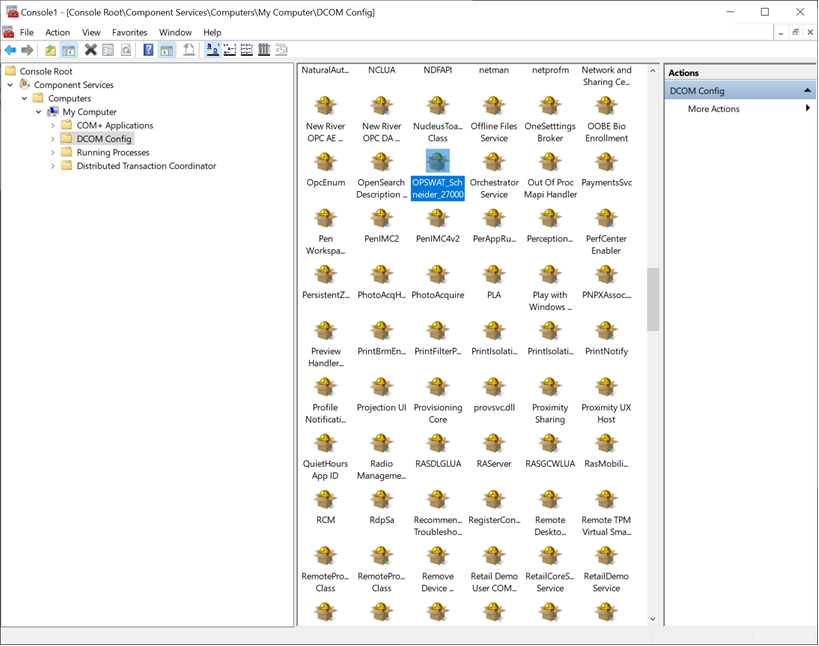
Right click the service and proceed with the desired configuration.
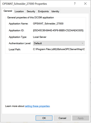
This process would allow you to configure any of the OPSWAT OPC DA DCOM services on the RED Flanker.