Introduction
The MetaDefender Optical Diode High Availability (HA) solution uses two sets of appliances and an appropriate appliance configuration. This ensures a high level of operational performance (uptime and dataflow).
Please, notice that High Availability feature is not available in MetaDefender Optical Diode Din Rail format.
High Availability is not supported on the Optical Diode Common Criteria EAL4+ certified software version (1.11.0 OD-101). To configure a High Availability pair, users must go to MyOPSWAT.com and download version (1.11.0 OD-102). Please note that 1.11.0 OD-102 is not Common Criterial EAL4+ certified.
High Availability feature supports the following:
- TCP Streams
- UDP Streams
- Vault(HTTP) Streams
- File Transfer
- Connectors
The strategy for high availability will utilize Active/Standby components, where one appliance will be in Active state at a given time. The other appliance will be in Standby, ready to take over should hardware in the active appliance fail.
Hardware Requirements
A pair of MetaDefender Optical Diode appliances will be combined in a logical unit to formulate Netwall HA. The prerequisite is that MetDefender Optical Diode appliances of same type are used to form the HA pair. Additionally, the switches to which the MetDefender Optical Diode appliances are connected must support multicast switching:
- Two BLUE MetDefender Optical Diode.
- Two RED MetDefender Optical Diode.
- Two switches supporting multicast switching one for BLUE side and one for the RED side.
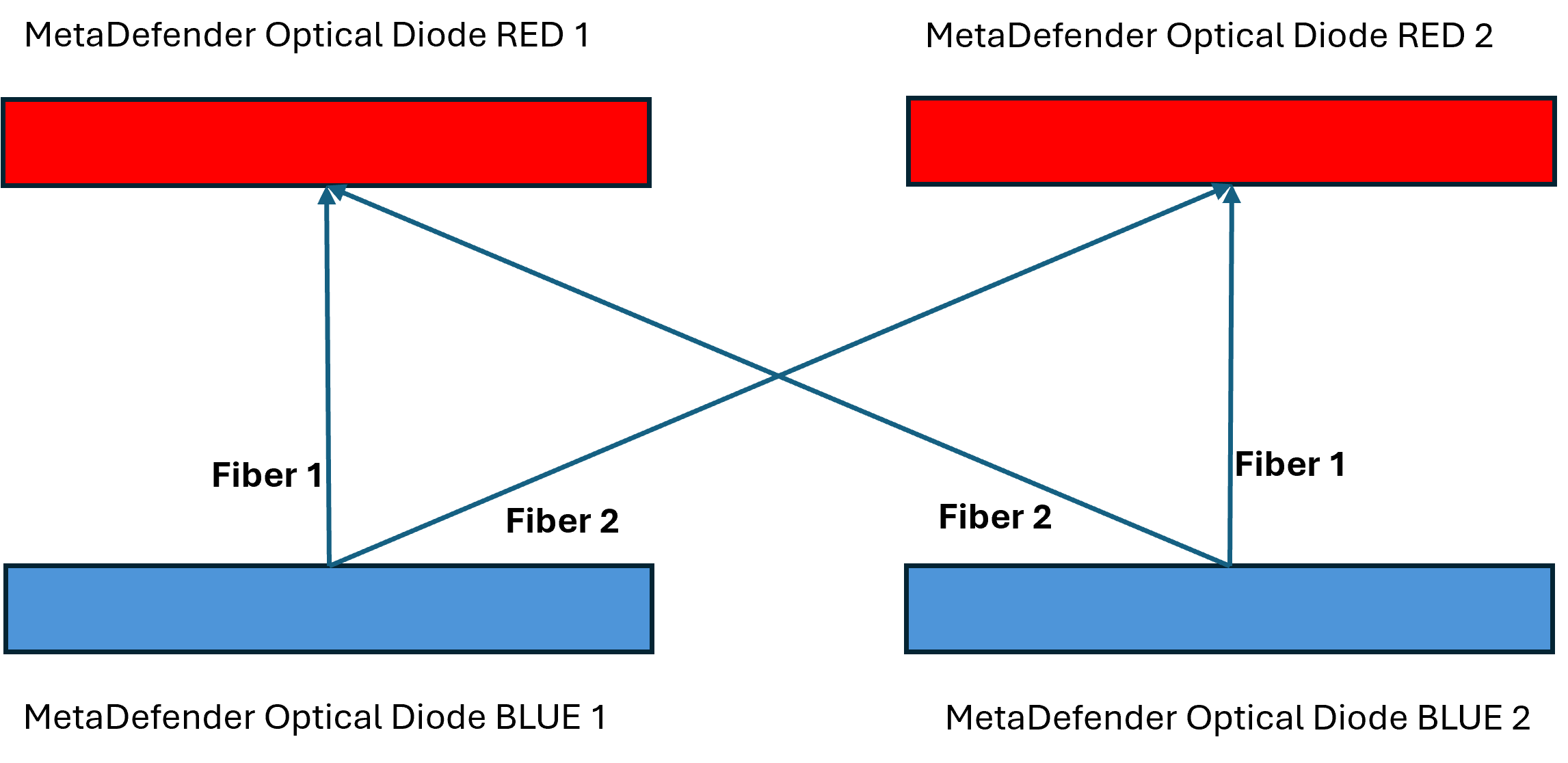
- Fiber cables need to be connected as it is displayed in the Figure. MetaDefender Optical Diode BLUE 1 Fiber 1 should be connected to the corresponding SFP in MetaDefender Optical Diode RED 1 and MetaDefender Optical Diode BLUE 1 Fiber 2 should be connected to MetaDefender Optical Diode RED 2. User should repeat this schema for MetaDefender Optical Diode BLUE 2 Fiber 1 and Fiber 2, connecting them respectively to MetaDefender Optical Diode RED 2 and MetaDefender Optical Diode RED 1.
Networking Requirements
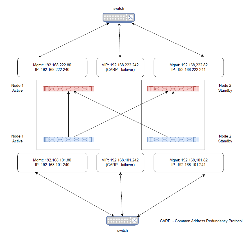
In order to function properly, ucarp requires a logical/real IP address on each domain of the HA-pair, and a single shared VIP on each domain for the HA-pair. So the IPs needed would be:
- Management IP for each MetaDefender Optical Diode BLUE.
- Additional IP for each MetaDefender Optical Diode BLUE.
- Management IP for each MetaDefender Optical Diode RED.
- Additional IP for each MetaDefender Optical Diode RED.
- Two Virtual IP (VIP) for Common Address Redundancy Protocol (CARP), one for BLUE side and one for RED side.
A VIP (Virtual IP address) is a shared IP that is used between either two BLUE or two RED NetWall computers. This VIP is only active on one of the MetaDefender Optical Diode appliances at any given time. The other appliance in the HA-pair, has the VIP interface down which places that VIP interface in standby mode. If a failover event occur, the system will force an election event (the event occurring when hardware failure is detected), and that election event will determine the state of each node’s VIP.
High Availability Setup
There are several steps a user shoud follow to properly configure High Availability.
- Connect the fiber cables as indicated before.
- Configure additional IPs in the 2 BLUE appliances and in the 2 RED appliances.
- Configure Virtual IPs in the 2 BLUE appliances and in the 2 RED appliances.
- Define Primary and Secondary servers.
- Configure Connectors for proper failover management.
Configure additional IPs
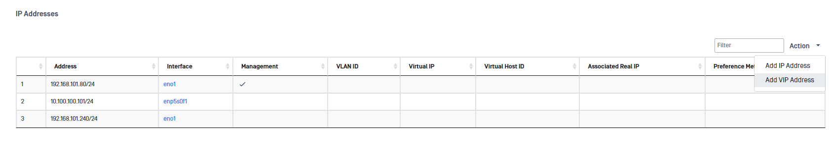
As mentioned before, MetaDefender Optical Diode will need an extra IP address per appliance for anbling logical separation between management IP network and the data IP network. This segregation ensures that managemnet WebUI is always accesible on the management IP network. To configure the additional IP go to Advanced -> Networking -> IP Addresses, deploy the Action button and click on Add IP Address, fill in the IP Address and Mask and click on Submit button.
Configure Virtual IPs
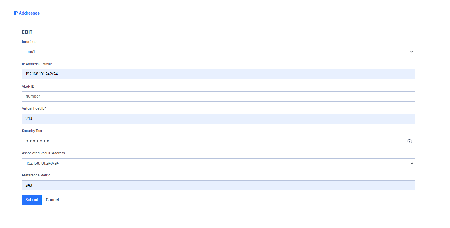
A VIP (Virtual IP address) is required as mentioned before. To configure the VIP go to Advaced -> Networking -> IP Addresses, deploy the Action button and click on Add VIP Address, fill in the mandatory fields click on Submit button.
You need to remember the Security text you define as this should be the same in both MetaDefender Optical Diodes (it should be the same between the two MetaDefender Optical Diode BLUE and again, the same between the two MetaDefender Optical Diode RED), so both appliances know they are part of the same HA system. In the image bellow, there is a configuration example.
Define Primary Server
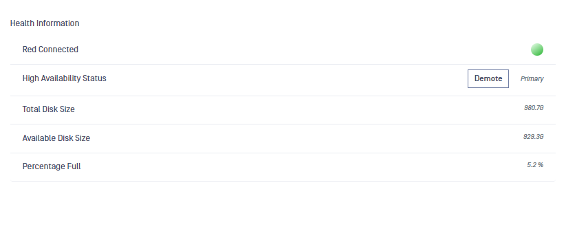
Once configured both appliances of the HA pair, user can check which one is the Primary appliance and which one is in Standby status in the Dashboard.
User can change this using the Demote button in the Primary appliance Dashboard. Once the user clicks on the Demote button, that appliance would become the secondary and would go to Stand by mode while the other appliance of the HA pair would become the Primary.
Configure Connectors
Connectors within MetaDefender Optical Diode are typically designed to be outbound clients (Blue domain and some Red domain) or servers (Red domain). Thus, when the connector is outbound client, no additional configuration is needed to ensure successful failover or election events. In the case where the connector is designed as server (Red domain) the VIP address is the one that should be used for clients that need to connect to it.